
Upper shell machine installing mechanism for oscillating motor

A technology of vibrating motors and mounting mechanisms, which is applied in metal processing, metal processing equipment, manufacturing tools, etc., can solve the problems of low efficiency of buckle shells, etc., and achieve the effect of ensuring accuracy and preventing excessive oil injection

Pending Publication Date: 2017-10-13
苏州市唯西芈电子科技有限公司
View PDF7 Cites 2 Cited by
  • Summary
  • Abstract
  • Description
  • Claims
  • Application Information

AI Technical Summary

Problems solved by technology

[0002] In the production of vibration motors, after the internal components of the vibration motor are installed, the oiling operation is performed first, and then the upper casing is buckled on the lower casing. At present, when the upper casing is installed, the upper casing operation is performed manually. Due to There is a gap on the side of the upper shell through which the FPCB passes. Therefore, when manually fastening the shell, it is necessary to align the gap of the upper shell with the FPCB, and then buckle the upper shell on the lower shell. At the same time, it has to go through an alignment operation, which requires a high degree of meticulousness of the operator, which makes the buckling efficiency low. At the same time, due to the small shape of the upper shell, it is inevitable that there will be no errors during the buckling operation.

Method used


Image

  • Upper shell machine installing mechanism for oscillating motor
  • Upper shell machine installing mechanism for oscillating motor
  • Upper shell machine installing mechanism for oscillating motor

Examples


Embodiment Construction

[0021] The present invention will be further described below in conjunction with the accompanying drawings and specific embodiments.

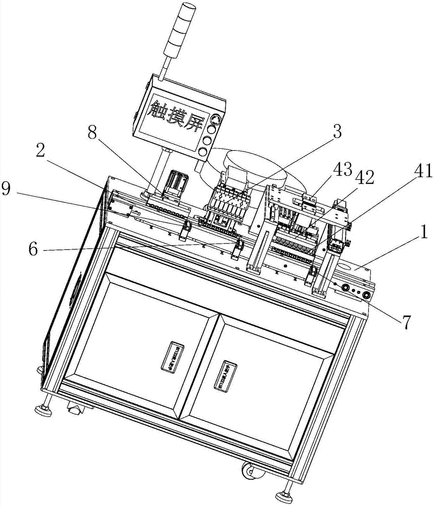
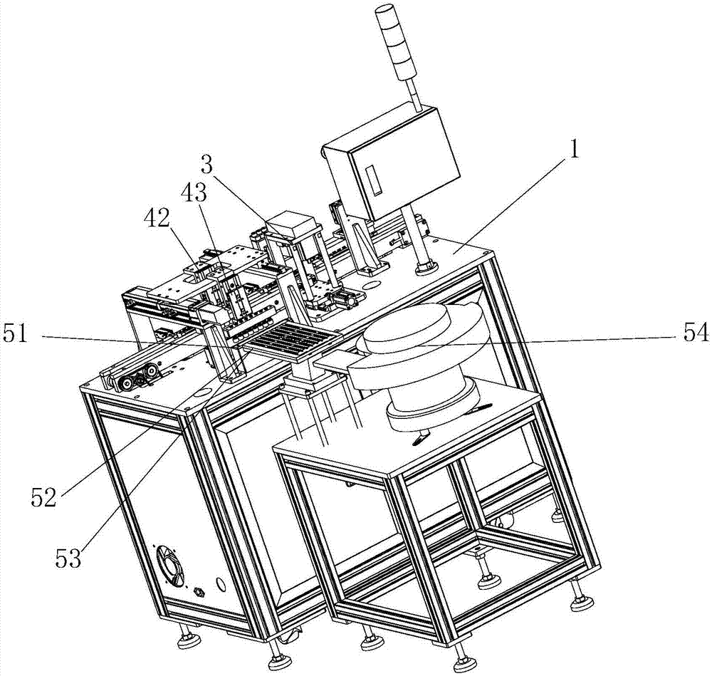
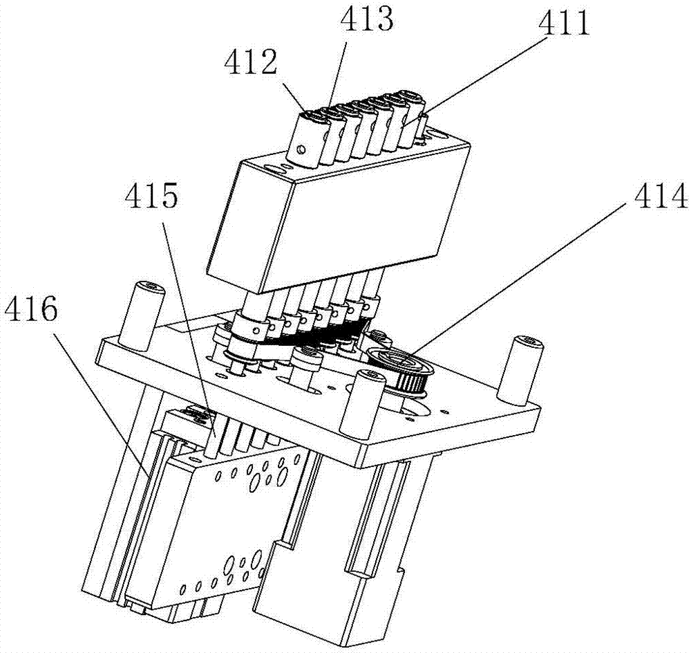
[0022] Such as Figure 1 to Figure 2 The shown upper casing machine installation mechanism for vibration motors includes a frame 1, on which a transmission device 2 for transferring turnover jigs is arranged, and one side of the transmission device 2 is respectively installed along the transmission direction of the transmission device 2 The oiling device 3 and the upper casing device also include a vibrating feeding mechanism for conveying the upper casing to the upper casing device. The side of the transmission device 2 is also provided with a first blocking mechanism 6 and a second blocking mechanism 7. The first blocking mechanism Mechanism 6 includes the first photoelectric sensor that detects whether the turnover fixture is in place and the first blocking cylinder that blocks the turnover fixture, and the second blocking mechanism 7 includ...


PUM


Abstract

The invention discloses an upper shell machine installing mechanism for an oscillating motor. The upper shell machine installing mechanism comprises a rack. The rack is provided with a conveying device used for conveying a circulating jig. An oiling device and an upper shell device are installed on one side of the conveying device in the conveying direction of the conveying device. The upper shell machine installing mechanism further comprises an oscillating feeding mechanism for conveying upper shells to the upper shell device. A first blocking mechanism and a second blocking mechanism are further arranged on the side edge of the conveying device and located below the oiling device and the upper shell device correspondingly. According to the upper shell machine installing mechanism, before the upper shells are installed, the oiling operation is carried out firstly, then the upper shells are buckled to lower shells, during the shell buckling operation, multiple upper shells can be buckled and installed at the same time, correction operation is carried out firstly before the shells are buckled and installed, accordingly, in the shell buckling process, notches of the upper shells can be aligned to FPCBs installed in the lower shells, and installing accuracy is ensured.

Description

technical field [0001] The invention relates to an assembly mechanism of a vibration motor, in particular to an installation mechanism of an upper casing used for a vibration motor. Background technique [0002] In the production of vibration motors, after the internal components of the vibration motor are installed, the oiling operation is performed first, and then the upper casing is buckled on the lower casing. At present, when the upper casing is installed, the upper casing operation is performed manually. Due to There is a gap on the side of the upper shell through which the FPCB passes. Therefore, when manually fastening the shell, it is necessary to align the gap of the upper shell with the FPCB, and then buckle the upper shell on the lower shell. At the same time, it has to go through an alignment operation, which requires a high degree of meticulousness of the operator, which makes the buckling efficiency low. At the same time, due to the small shape of the upper sh...

Claims


Application Information

Patent Timeline
Patent Type & Authority Applications(China)
IPC IPC(8): B23P19/00B23P19/10
CPCB23P19/00B23P19/001B23P19/10
Inventor 陶为银
Owner 苏州市唯西芈电子科技有限公司
Learn More