A Piston Ring Radial Rigidity Testing Device

A technology of radial stiffness and testing device, applied in the field of power devices, can solve the problems of influence and inability to test with non-isobaric rings, and achieve the effects of high efficiency, high practicability and simple testing operation.

Active Publication Date: 2019-09-27
HARBIN ENG UNIV
View PDF7 Cites 0 Cited by
  • Summary
  • Abstract
  • Description
  • Claims
  • Application Information

AI Technical Summary

Problems solved by technology

[0003] The patent of notification number CN102374931A provides a kind of measuring device about the tension of the piston ring. The device is wound on the piston ring through a steel belt fixed on the bracket at one end, and the pulling of the steel belt makes the piston ring shrink so that the gap is equal to that of the piston. The gap in the actual cylinder liner, and then the tension of the piston ring can be obtained by measuring the tension on the rope, but the friction force of the rope on the piston ring will affect the accuracy of the test results
In the patent with the notification number CN201066316Y, the steel belt is connected to the vibration mechanism, and the friction between the rope and the ring is reduced as much as possible through the vibration of the steel belt, but the influence still exists
Moreover, the current piston ring test device is basically suitable for isobaric rings, and cannot be used for non-isobaric ring tests

Method used


Image

  • A Piston Ring Radial Rigidity Testing Device
  • A Piston Ring Radial Rigidity Testing Device
  • A Piston Ring Radial Rigidity Testing Device

Examples


Embodiment Construction

[0019] The device will be described in detail below with reference to the accompanying drawings.

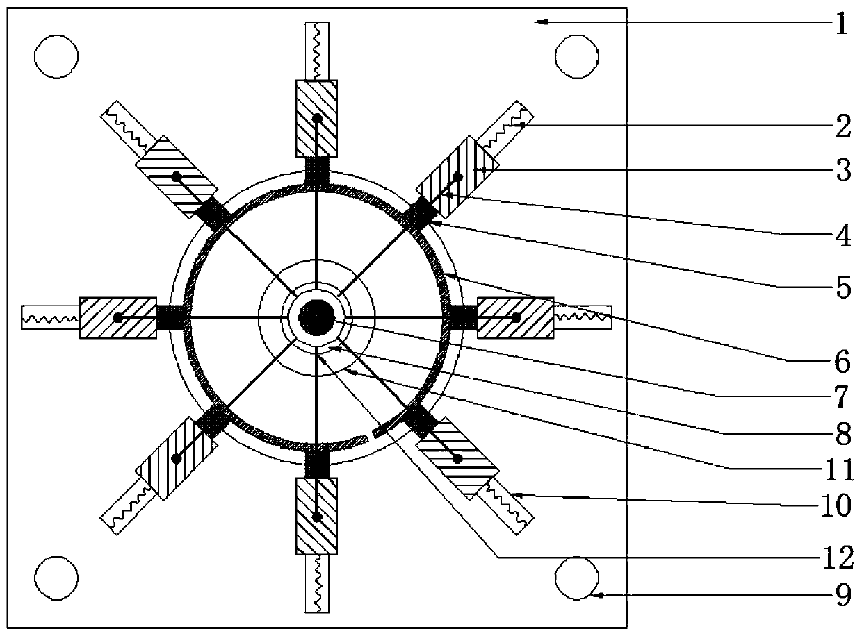
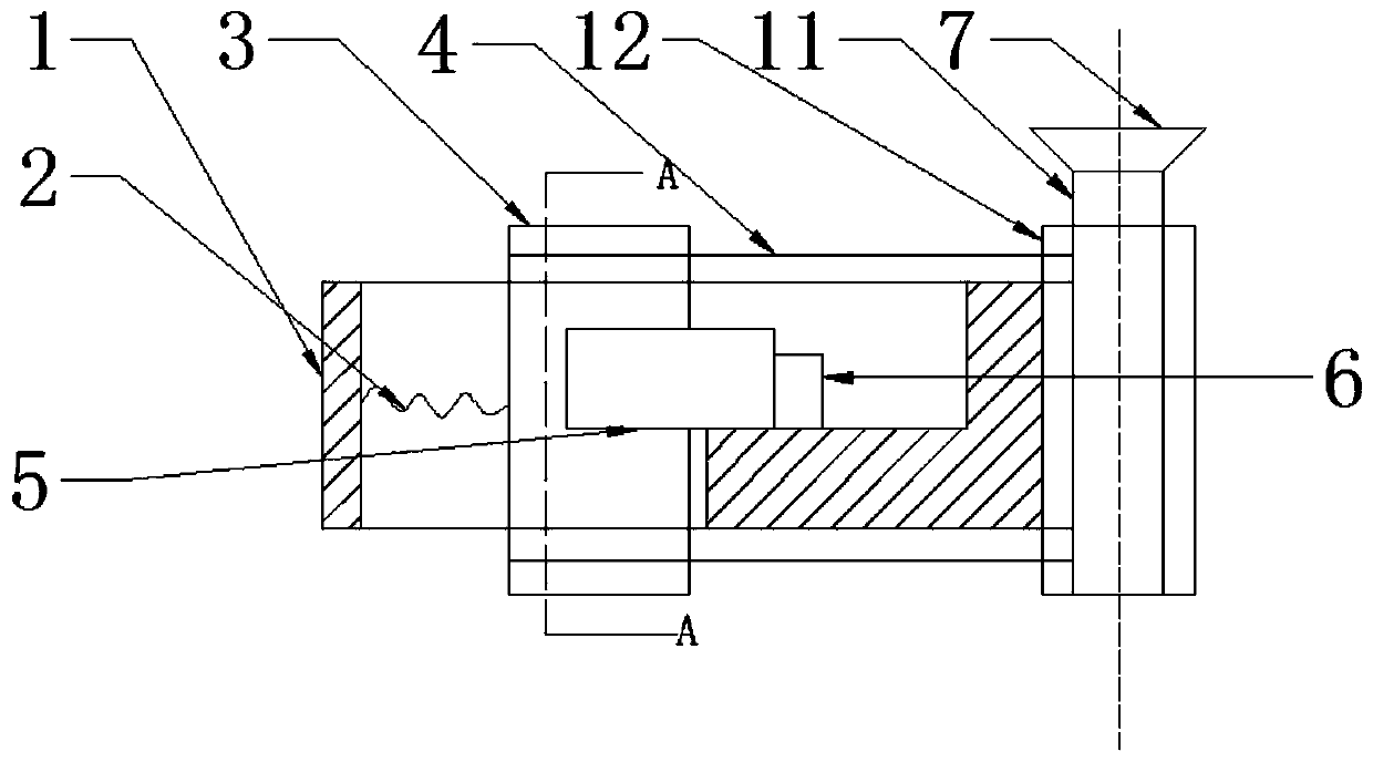
[0020] like figure 1 As shown, a piston ring 6 radial stiffness test device includes: a fixed platform 1, a rotating table and a test assembly; the test assembly includes a tension spring 2, a top column 3, a pressure sensor 5 and a rigid rope 4, such as figure 2 shown; the rotary table includes a knob 7 and a stud 8;

[0021] The fixed platform 1 is fixed on the horizontal foundation base; the middle of the fixed platform 1 has an annular pit; the center of the pit is a circular hollow and a rotary table is installed. The column 8 is installed in the inner threaded pipe 12, and there is a knob 7 on the stud 8; there is a chute 10 along the circumferential direction of the pit, and the test component is installed in the chute 10; the side wall of the chute 10 and the top column 3 side are pulled The spring 2 is connected, and the other side of the top column 3 has a groove mat...


PUM


Abstract

The invention discloses a testing device of the radial rigidity of a piston ring. The testing device comprises a fixed platform, a rotating table and a testing assembly, wherein the testing assembly comprises a tension spring, a back-up post, a pressure sensor and a rigid rope; the fixed platform is fixed on a horizontal base; an annular drop pit is formed in the middle of the fixed platform; the position of the center of circle of the drop pit is round and hollow, and the rotating table is installed in the position; the rotating table comprises a rifled tube, a knob and a bolt, the bolt is installed in the rifled tube, and the knob is arranged on the bolt; a sliding chute is formed along the circumference direction of the drop pit, and the testing assembly is installed in the sliding chute; the side wall of the sliding chute is connected with one side of the back-up post, and a groove matched with the pressure sensor is formed at the other side of the back-up post and used for installing the pressure sensor; the pressure sensor is abutted against the outer side of the piston ring; and bosses are respectively arranged at the upper and lower ends of the back-up post, one end of the rigid rope is wound on the bosses, and the other end of the rigid rope is wound on the bolt. The testing device of the radial rigidity of the piston ring avoids the influence of friction force in the traditional method, and is simple in testing operation, high in efficiency, applicable to constant wall pressure rings and non-constant wall pressure rings, and high in practicability.

Description

technical field [0001] The invention belongs to the field of power devices, and in particular relates to a piston ring radial stiffness testing device. Background technique [0002] In order to meet the air tightness requirements of the piston ring, the piston ring must have a certain radial stiffness when installed in the cylinder liner. The radial stiffness of the piston ring depends on the tension of the piston ring, and has a great influence on the performance of the piston ring, and is a very important parameter for the calculation and analysis of the piston ring. Therefore, it is of great engineering significance to test the radial stiffness of piston rings. [0003] The patent with the publication number CN102374931A provides a measuring device about the tension of the piston ring. The device is wound on the piston ring through a steel belt fixed on the bracket at one end, and the piston ring is contracted by the pulling of the steel belt to make the gap equal to the...

Claims


Application Information

Patent Timeline
Patent Type & Authority Patents(China)
IPC IPC(8): G01M13/00
Inventor 卢熙群罗江龙董庆兵赵滨李彤阳王乃昆张亮吕修颐周帅宇黄福战
Owner HARBIN ENG UNIV
Why Eureka
Try Eureka