A loading test device

A loading test device and horizontal loading technology, applied in the direction of using stable shear force to test material strength, using stable tension/pressure to test material strength, etc., can solve the problems of high energy consumption, high price, high test cost, etc. , to achieve the effect of ensuring accurate distribution and solving the effect of friction

Inactive Publication Date: 2017-04-19
NANJING UNIV OF AERONAUTICS & ASTRONAUTICS
View PDF5 Cites 0 Cited by
  • Summary
  • Abstract
  • Description
  • Claims
  • Application Information

AI Technical Summary

Problems solved by technology

[0003] For a long time, it has been very difficult to achieve low cost for this type of material testing
At present, it can be realized by using a two-way hydraulic servo testing machine, but because these equipment are expensive, they have strict requirements on the use environment, and high energy consumption requires high test costs.

Method used


Image

  • A loading test device
  • A loading test device

Examples


Embodiment Construction

[0014] The present invention will be described in detail below in conjunction with the accompanying drawings.

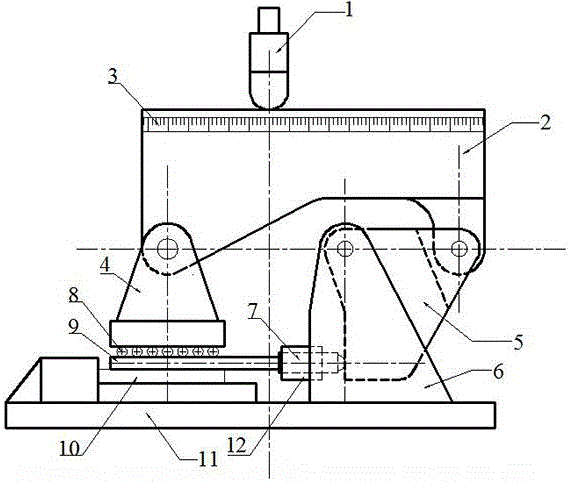
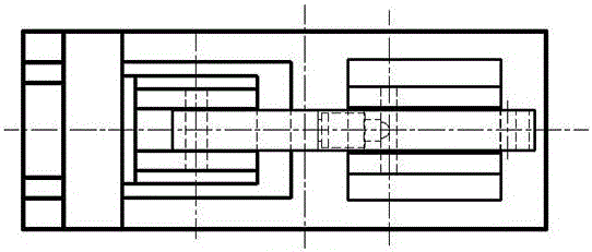
[0015] Such as figure 1 , figure 2 As shown, the present invention mainly includes a base 11, a steering plate 5, a load distribution beam 2, a ballast head 4, and a horizontal loading plate 9; one end of the base is provided with a fixed blocking plate, and the other end is provided with a fixed U-shaped horizontal support 6 The opening direction of the horizontal support 6 is far away from the blocking plate, and the convex portion 12 of the opening is provided on the horizontal support near the blocking plate surface, and the long cylindrical horizontal loading head 7 is placed in the convex portion 12, and the length of the convex portion 12 is less than The length of the horizontal loading head 7; one end of the steering plate 5 is hinged with the upper ends of the two wings of the horizontal support 6, and the other end of the steering plate 5 is hinged with ...


PUM


Abstract

The invention discloses a load test device. The load test device comprises a base, a deflecting plate, a load distribution beam, a ballast head and a horizontal load plate; one end of the base is provided with a fixed baffle plate, and the other end of the base is provided with a fixed U-shaped horizontal supporting seat; the opening direction of the horizontal supporting seat is away from the baffle plate, a convex part of an opening is arranged on the surface, adjacent to the baffle plate, of the horizontal supporting seat, and a long cylindrical horizontal load head is arranged in the convex part; one end of the deflecting plate is hinged to two wings of the horizontal supporting seat, and the other end of the deflecting plate is hinged to one end of the load distribution beam and can rotate; the other end of the load distribution beam is hinged to the ballast head, the horizontal load plate is arranged below the ballast head, and a joined bearing is arranged between the ballast head and the horizontal load plate. The total load is divided into the ballast and the horizontal plane shearing load by virtue of the load distribution beam according to a lever principle, and the vertical load and the horizontal load can be synchronously applied to a test piece by utilizing one centralized load point, so that the problem that ballast and surface shearing composite load requirement cannot be satisfied by a pressure machine and a universal test machine can be solved.

Description

technical field [0001] The invention relates to the field of structural experiment mechanics, in particular to a loading test device. Background technique [0002] In aviation, navigation, transportation, road and bridge, building, and port engineering structures, the structural parts composed of various materials are complex stress-bearing members, and they are all under complex stress states in various environments for a long time, so these The strength of components under various environments is an important research topic in structural mechanics. Especially in the design of modern engineering structures, it is necessary to study the strength of structures under complex loads and environments. It is urgent to implement complex loads and various environmental conditions on various materials in the laboratory to assess the mechanical strength of materials. , to provide a scientific basis for structural design, and to prepare for the next step of theoretical establishment. ...

Claims


Application Information

Patent Timeline
Patent Type & Authority Patents(China)
IPC IPC(8): G01N3/08G01N3/24
Inventor 汪勇汤剑飞汪浩文毛春见
Owner NANJING UNIV OF AERONAUTICS & ASTRONAUTICS
Why Eureka
Try Eureka