Pressure measuring device
A measuring device and pressure technology, which is applied in the field of sensors, can solve the problems such as the inability to arrange the life of the sensor and the limitation, and achieve the effect of simple structure, good control, reliability and stability
- Summary
- Abstract
- Description
- Claims
- Application Information
AI Technical Summary
Problems solved by technology
Method used
Image
Examples
no. 1 example
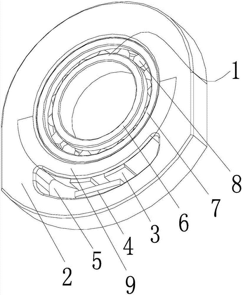
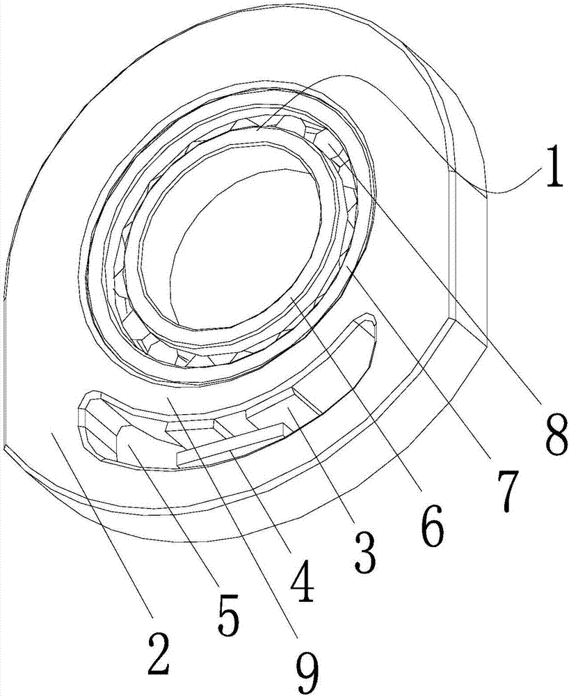
[0033] see figure 1 and figure 2 :
[0034] A pressure measuring device, comprising a bearing 1, a bearing sleeve 2 and a force sensor 3, the bearing 1 is arranged in the bearing sleeve 2, the force sensor 3 is arranged on the bearing sleeve 2, and the bearing sleeve 2 is provided with a bearing mounting position 12 and a force sensor 3 The installation position, the bearing installation position 12 and the force sensor 3 installation positions are respectively arranged on both sides of the partition, specifically:
[0035] see figure 1 , the bearing sleeve 2 can be in any shape, the bearing sleeve 2 is designed with an oval hole or other irregular arc-shaped holes, a circular bearing installation position 12 and a sensor installation position 5 are formed through the partition, and the bearing installation position 12 It is separated from the sensor installation position 5 by a partition, the partition is arc-shaped, the outer diameter of the partition is larger than the ...
no. 2 example
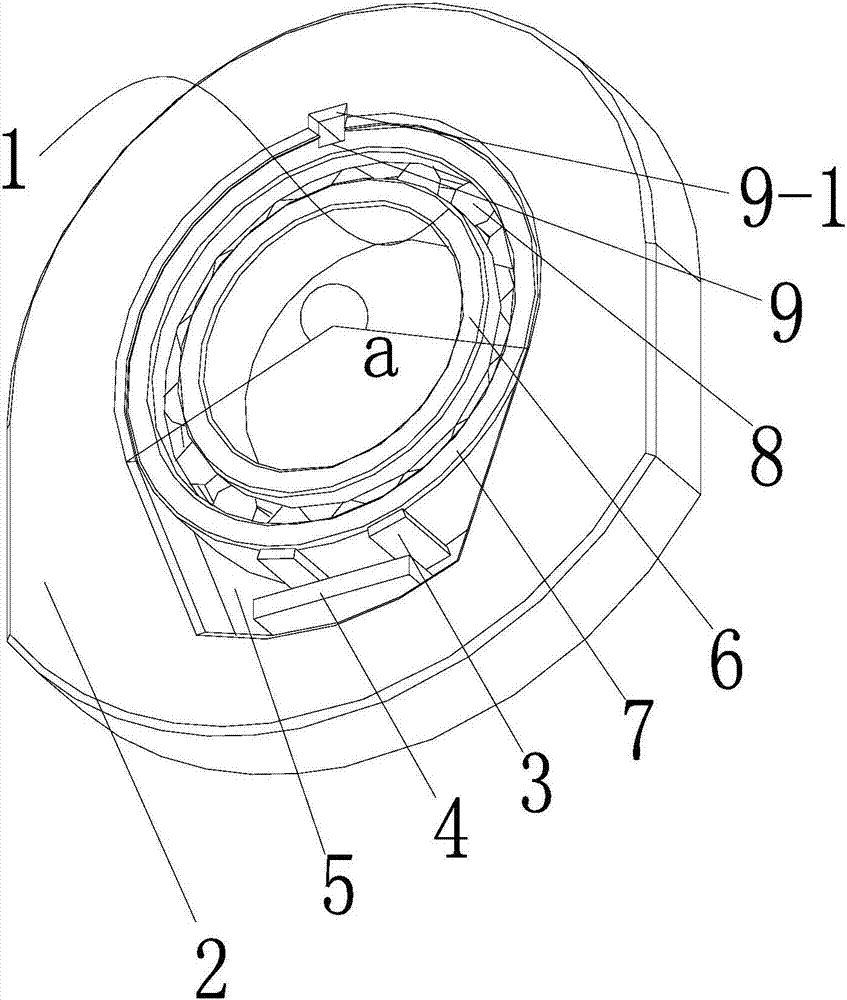
[0040] see image 3 and Figure 4 ,
[0041] A pressure measuring device, comprising a bearing 1, a bearing sleeve 2 and a force sensor 3, the bearing 1 is arranged inside the bearing sleeve 2, the force sensor 3 is arranged outside the bearing 1, and the bearing sleeve 2 is provided with a bearing mounting position 12 and a force sensor 3 The installation position, the bearing installation position 12 and the force sensor 3 installation position are not directly connected through the partition, specifically:
[0042] see image 3 , the bearing sleeve 2 can be in any shape, and the bearing sleeve 2 is designed with an oval hole or other irregular arc holes, and the arc or oval hole is composed of a circular bearing mounting position 12 and a sensor mounting position 5 And a direct connection is formed. Wherein, the bearing mounting position 12 is half a circle, and the bearing mounting position 12 can form a half-covered structure for the bearing 1, and the bearing sleeve ...
no. 3 example
[0048] see Figure 5 , this picture shows the application of the pressure measuring device on the torque sensor of the bicycle center shaft. The bearing sleeve 2 is integrated with the end cover of the torque center shaft. The bearing installation position 12 and the sensor installation position 5 are set on the end cover. The bearing installation position 12 is an arc state, the end of the bearing installation location 12 is connected to the sensor installation location 5, the bearing installation location 12 is directly connected to the sensor installation location 5, the two sides of the sensor installation location 5 are tangent to the end of the bearing installation location 12, and the bearing installation location 12 The cladding angle formed by the connection between the two ends and the rotation axis of the bearing 1 is 220°. The bearing installation position 12 is also provided with a keyway 9, and the bearing installation position 12 is provided with a bearing 1. The...
PUM
 Abstract
Description
Claims
Application Information
 - R&D Engineer
- R&D Manager
- IP Professional
- Industry Leading Data Capabilities
- Powerful AI technology
- Patent DNA Extraction
Browse by: Latest US Patents, China's latest patents, Technical Efficacy Thesaurus, Application Domain, Technology Topic, Popular Technical Reports.
© 2024 PatSnap. All rights reserved.Legal|Privacy policy|Modern Slavery Act Transparency Statement|Sitemap|About US| Contact US: help@patsnap.com


