Ventilation fan with linkage type air port valve
A technology for tuyere valves and ventilating fans, which is applied in the direction of non-variable pumps, machines/engines, pump control, etc., and can solve problems such as the inability to realize the air flow in the air duct and the inability to close the vents, so as to avoid poor interception effect and increase The effect of air velocity
- Summary
- Abstract
- Description
- Claims
- Application Information
AI Technical Summary
Problems solved by technology
Method used
Image
Examples
Embodiment 1
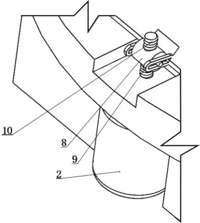
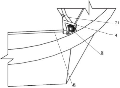
[0027] combined with Figure 1-3 As shown, a ventilation fan with a linkage type tuyere valve includes a body 1 with a regular hexagonal or circular cross section. The direction is the same, any end of the body 1 along the axial direction is fixedly connected with a ring-shaped fixed ring 3, and the fixed ring 3 is provided with a six-leaf linkage tuyere valve with a stabilizing effect, and the tuyere valve includes Relative to the six equilateral triangular baffles 7 installed on the upper surface of the fixed ring 3, the baffles 7 are hinged to the mounting seat 4 arranged on the fixed ring 3, and the bottom edge of the baffles 7 is fixed A rotating shaft 6 welded parallel to the bottom is connected, and the two ends of the rotating shaft 6 pass through the mounting seat 4 and are connected with a bevel gear 5, and the bevel gears 5 at the two ends of the adjacent two interceptor plates 7 mesh with each other; wherein, Two parallel rocker arms 9 are fixedly installed in the...
Embodiment 2
[0031] In order to further realize the present invention, on the basis of Embodiment 1, further, this embodiment adopts the following settings: the lifting mechanism includes a drive motor 2 that is detachably and fixedly connected to the lower surface of the fixed ring 3 The drive shaft of the drive motor 2 runs through the fixed ring 3 and the drive shaft of the protruding part is provided with external threads, the drive shaft is threaded with a push-pull block 8, and the two ends of the push-pull block 8 are integrally connected with a rocker along the length direction. Rod, the rocking rod is inserted in the bar-shaped hole provided along the length direction of the rocking arm 9 and the diameter of the rocking rod is smaller than .
[0032] Working principle: When the lifting mechanism needs to rise, the drive motor 2 rotates forward, and the push-pull block 8 rises along the drive shaft under the thread cooperation of the drive shaft. During the rising process, the push-...
Embodiment 3
[0034] In order to further realize the present invention, on the basis of Embodiment 1, further, this embodiment particularly adopts the following settings: the lifting mechanism includes a lifting rod hinged with the free end of the rocker arm 9, and the lifting The rod runs through the fixed ring 3 and is driven and connected to the drive motor 2 fixedly installed on the lower surface of the fixed ring 3. The elevating rod is provided with a rack, and the rack is meshed with the gear on the drive shaft of the drive motor 2. By driving The forward and reverse motion of the motor 2 drives the elevating rod to move up and down, so as to realize the purpose of controlling the free end of the rocker arm 9 to swing up and down. Because the rocker arm 9 and the cutoff plate 7 are fixedly connected, the purpose of controlling the cutoff plate 7 is achieved. The specific structure of the free end of the rocking arm 9 hinged lifting rod described in this embodiment is: the rocking arm ...
PUM
 Abstract
Description
Claims
Application Information
 - R&D
- Intellectual Property
- Life Sciences
- Materials
- Tech Scout
- Unparalleled Data Quality
- Higher Quality Content
- 60% Fewer Hallucinations
Browse by: Latest US Patents, China's latest patents, Technical Efficacy Thesaurus, Application Domain, Technology Topic, Popular Technical Reports.
© 2025 PatSnap. All rights reserved.Legal|Privacy policy|Modern Slavery Act Transparency Statement|Sitemap|About US| Contact US: help@patsnap.com


