
Continuous punching device for hinge blade

A technology of punching device and blade, which is applied in the direction of positioning device, clamping device, boring/drilling, etc., can solve the problems of weak clamping, low drilling efficiency, and affecting the accuracy of drilling, so as to avoid artificial The effect of positioning operation, high drilling efficiency and simple structure

Inactive Publication Date: 2017-10-10
FOSHAN SUCCEED AUTOMATIC TECH
View PDF5 Cites 21 Cited by
  • Summary
  • Abstract
  • Description
  • Claims
  • Application Information

AI Technical Summary

Problems solved by technology

Hinges are mainly installed on doors and windows, and hinges are more installed on cabinets. In the use of hinges, but in some cases, longer hinges are required. Long hinges may need to be punched during processing, and generally The drilling operation of the hinge blade is manual positioning and drilling, and the position of the long hinge needs to be drilled. Many times of manual positioning and drilling are required, resulting in low drilling efficiency. At the same time, the pressing of the drilling requires manual clamping. , the clamping is not firm, which affects the accuracy of punching

Method used


Image

  • Continuous punching device for hinge blade
  • Continuous punching device for hinge blade

Examples


Embodiment Construction

[0014] The following will clearly and completely describe the technical solutions in the embodiments of the present invention with reference to the accompanying drawings in the embodiments of the present invention. Obviously, the described embodiments are only some, not all, embodiments of the present invention. Based on the embodiments of the present invention, all other embodiments obtained by persons of ordinary skill in the art without making creative efforts belong to the protection scope of the present invention.

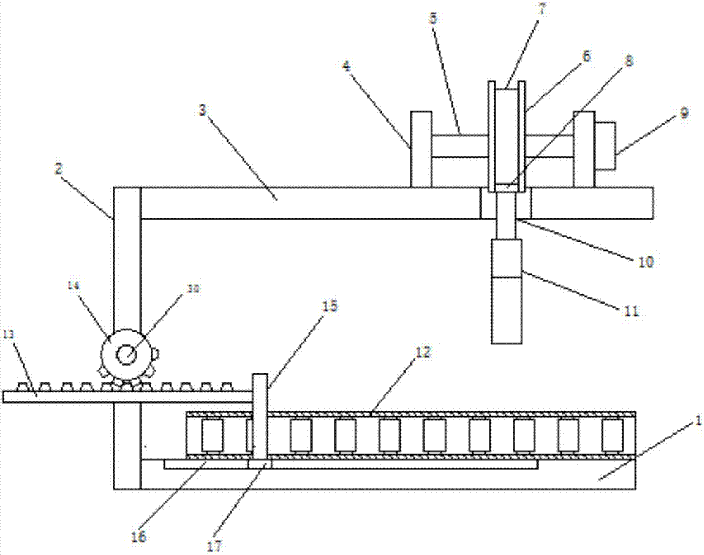
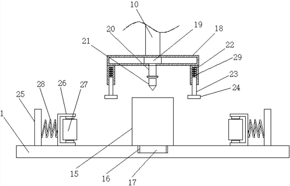
[0015] see Figure 1~2 , in an embodiment of the present invention, a hinge blade continuous punching device includes a bottom plate 1, a left side plate 2 and a top plate 3, the left side plate 2 is fixedly connected to the upper end surface of the bottom plate 1, and one end of the top plate 3 is connected to the left side The top of the plate 2 is fixedly connected, the base plate 1 is provided with a chute 16, the chute 16 is provided with a slider 17 slid...


PUM


Abstract

The invention discloses a continuous punching device for a hinge plate. The continuous punching device comprises a bottom plate, a left side plate and a top plate, wherein a slide slot is formed in the bottom plate; a slide block which is in sliding connection with the slide slot is arranged in the slide slot; the upper end of the slide block is fixedly connected with a pushing plate; the left side of the pushing plate is equipped with a rack; a pushing motor is arranged on the left side plate; an incomplete gear is arranged on the rotary shaft of the pushing motor; the incomplete gear is engaged with the rack; two opposite limiting devices are further arranged on the bottom plate; a cam is mounted on a transverse shaft; a hanger rod is arranged below the cam; the top end of the hanger rod is connected with the edge of the cam through a slide mechanism; and the lower end of the hanger rod is equipped with a drilling device. The continuous punching device is simple in structure, does not need manual operation for punching, reduces labor intensity, is suitable for continuously punching a long hinge, is relatively high in punching efficiency, is accurate in punching position and is relatively high in practicability.

Description

technical field [0001] The invention relates to hinge production equipment, in particular to a continuous punching device for hinge blades. Background technique [0002] A hinge, also known as a hinge, is a mechanical device used to connect two solids and allow rotation between them. Hinges may be constructed from moving components, or from materials that fold. Hinges are mainly installed on doors and windows, and hinges are more installed on cabinets. In the use of hinges, but in some cases, longer hinges are required. Long hinges may need to be punched during processing, and generally The drilling operation of the hinge blade is manual positioning and drilling, and the position of the long hinge needs to be drilled. Many times of manual positioning and drilling are required, resulting in low drilling efficiency. At the same time, the pressing of the drilling requires manual clamping. , The clamping is not firm, which affects the accuracy of punching. Contents of the in...

Claims


Application Information

Patent Timeline
Patent Type & Authority Applications(China)
IPC IPC(8): B23B41/00B23Q7/00B23Q3/00
CPCB23B41/00B23Q3/002B23Q7/00B23Q2703/10
Inventor 钟云华
Owner FOSHAN SUCCEED AUTOMATIC TECH
Learn More