Steam trap valve for tire vulcanizing machine

A tire vulcanization and steam trap technology, applied in steam traps, mechanical equipment, etc., can solve the problems of unstable sealing performance, poor working reliability, steam leakage, etc., and achieve rapid and accurate opening and closing, stable working performance and reasonable structure. advanced effects

Pending Publication Date: 2017-10-03
盐城易宝路轮胎有限公司
View PDF5 Cites 0 Cited by
  • Summary
  • Abstract
  • Description
  • Claims
  • Application Information

AI Technical Summary

Problems solved by technology

[0003] In the existing free-floating ball trap, under actual working conditions, the medium in the valve cavity is a two-phase mixture of high-temperature steam and high-temperature condensed water, and its dynamic changes make the floating ball unstable, and the trap will be in a state of being open. In the seemingly closed state, the opening and closing action of the trap is not obvious, and the steam (gas) leakage of the trap is relatively large, which has the problems of unstable sealing performance and poor working reliability.
If the pressure of the medium in the pipeline is too high, or the temperature does not reach the temperature difference required for the change of the metal film, the air cannot be removed, the floating ball will fail, and the valve will not be closed tightly, resulting in steam leakage and the consequence of not being able to achieve air blocking and drainage. At the same time, sometimes the process requires that the temperature drop rapidly, but the current steam trap pipe is too small, and it is difficult to drain the liquid in a short time, resulting in a slow temperature drop
[0004] To sum up, the steam traps used in vulcanizing machines in the tire manufacturing process currently have the problems of unstable sealing performance and flow that cannot meet the needs of certain working conditions

Method used


Image

  • Steam trap valve for tire vulcanizing machine
  • Steam trap valve for tire vulcanizing machine

Examples


Embodiment Construction

[0017] The following will clearly and completely describe the technical solutions in the embodiments of the present invention with reference to the accompanying drawings in the embodiments of the present invention. Obviously, the described embodiments are only some, not all, embodiments of the present invention. Based on the embodiments of the present invention, all other embodiments obtained by persons of ordinary skill in the art without making creative efforts belong to the protection scope of the present invention.

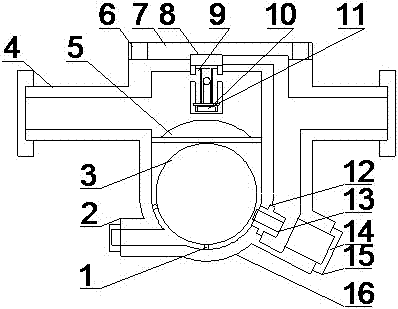
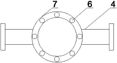
[0018] see Figure 1-2 , the present invention provides a technical solution: a steam trap for a tire vulcanizer, comprising a valve body 16, a main valve seat 15 and an auxiliary valve body 8, the main valve seat 15 is arranged through the lower right part of the valve body 16, and the auxiliary valve body 8 Set at the upper center of the valve body 16, the top of the valve body 16 is fixed with a bonnet 7, and the sub-valve body 8 is welded under the bonnet ...


PUM


Abstract

The invention discloses a steam trap valve for a tire vulcanizing machine. An auxiliary valve body is welded to the lower portion of a valve lid and composed of an auxiliary valve piece, an auxiliary valve lid and an auxiliary valve passage; and the auxiliary valve piece is arranged in a cavity formed by connecting the auxiliary valve body and the valve lid, an insulation cover is fixedly mounted below the auxiliary valve body, and a floating ball is arranged below the insulation cover and supported through a plurality of guiding columns. According to the steam trap valve for the tire vulcanizing machine, the structure is simple, and using is convenient; by adopting a novel multi-guiding-column structure, multi-point positioning is formed in the floating ball sealing process, and under the effect of multi-point positioning, alignment of the floating ball in the sealing process is accurate, so that the problems that the valve is not completely opened or closed, thus the air leakage quantity is large, and the sealing performance is instable are solved; and by arranging the structure of the auxiliary valve body, the effects that body cavity air is rapidly and effectively exhausted, starting and stopping of the floating ball are rapid and accurate, and the water discharge quantity is large are achieved, and the problems that the requirements for all working conditions cannot be met, and as sealing of the valve is not tight, steam leakage is caused and thus air resistance and water discharge cannot be achieved are avoided.

Description

technical field [0001] The invention relates to the field of tire manufacturing, in particular to a steam trap for a tire vulcanizer. Background technique [0002] The normal operation of the steam trap greatly affects the performance and efficiency of the vulcanizing machine in the tire manufacturing process. At the same time, it also affects the service life of the equipment, and sometimes brings unexpected vicious accidents, causing huge losses to the enterprise. Therefore, it is very important to choose a good trap. [0003] In the existing free float trap, under actual working conditions, the medium in the valve cavity is a two-phase mixture of high-temperature steam and high-temperature condensed water, and its dynamic changes make the float unstable, and the trap will be in a state of being open. In the seemingly closed state, the opening and closing action of the trap is not obvious, and the steam (gas) leakage of the trap is relatively large, which has the problem...

Claims


Application Information

Patent Timeline
Patent Type & Authority Applications(China)
IPC IPC(8): F16T1/22F16T1/38F16T1/40F16T1/45
CPCF16T1/22F16T1/383F16T1/40F16T1/45
Inventor 李建军
Owner 盐城易宝路轮胎有限公司
Why Eureka
Try Eureka