
Inertial wind power generation device

A wind power generation device and inertial technology, which is applied in the direction of wind power generation, wind engine, wind motor combination, etc., can solve the problems of difficult maintenance, high cost, and high cost of the device, and achieve a small footprint, low noise, and low cost. Effect

Pending Publication Date: 2017-10-03
NANJING GREEN NEW ENERGY RES INST CO LTD
View PDF0 Cites 0 Cited by
  • Summary
  • Abstract
  • Description
  • Claims
  • Application Information

AI Technical Summary

Problems solved by technology

For a long time, wind power generators have been monopolized by large foreign companies, which are expensive, difficult to maintain, and expensive

Method used


Image

  • Inertial wind power generation device
  • Inertial wind power generation device
  • Inertial wind power generation device

Examples


Embodiment 1

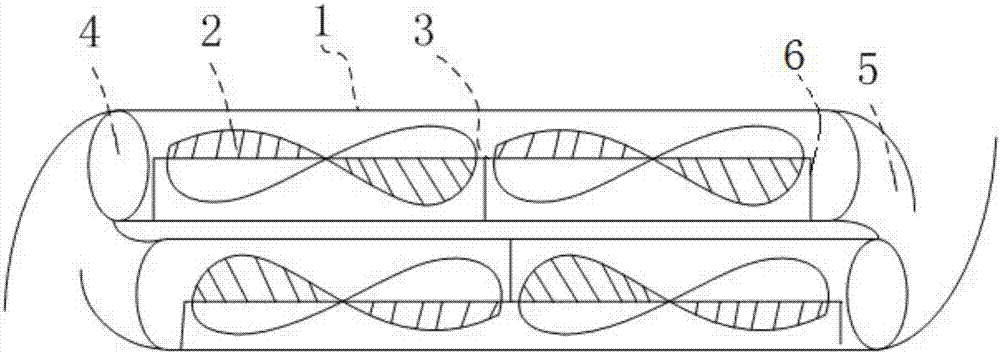
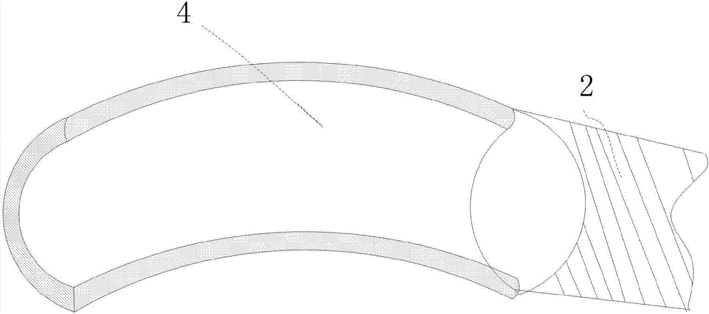
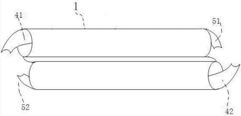
[0029] A kind of inertial wind power generation device, said device includes two sets of identical systems, such as figure 1 As shown, the specific device has a ventilation channel 1, a wind wheel 2, a rotating shaft 3, an air inlet 4 and an air outlet 5; the number of the wind wheels is preferably two, and the two wind wheels 2 are fixed in the ventilation channel 1 through the rotating shaft 3 , the rotating shaft is connected to the generator core; the air inlet 4 and the air outlet 5 are located on both sides of the ventilation channel 1; the two systems are misplaced and connected end to end to ensure that the wind from the air outlet of one system can enter the other again The air inlet of the system achieves the purpose of recycling. Such as figure 2 As shown, the ventilation channel is cylindrical, and the air inlet 4 and the air outlet 5 are characterized in that the air outlet is semi-cylindrical (that is, the cylindrical surfaces at both ends of the ventilation ch...

Embodiment 2

[0031] The two identical systems are alignment devices, and the wind power generation device includes a plurality of alignment devices arranged side by side. Such as Figure 4 As shown, the device can be placed on the green belt in the middle of the expressway. Because the device occupies a very small area, many of them can be placed side by side to further improve the power generation efficiency. When the car on the left is driving from bottom to top and passes through the air intake of the device, due to inertia, a very strong wind will blow into the air intake. At this time, the wind force will drive the wind wheel to rotate, thereby achieving the purpose of generating electricity. After the wind comes out of the air outlet, due to the design of the semi-cylindrical air outlet, it will enter the air inlet of another system again and be used again. In the same way, when the right car is driving from top to bottom, the above process will also occur. Therefore, the device c...


PUM


Abstract

The invention discloses an inertial wind power generation device which comprises two same systems. Each system specially comprises a ventilation channel, wind wheels, a rotating shaft, an air inlet and an air outlet, wherein the two wind wheels are fixed in the ventilation channel through the rotating shaft, the rotating shaft is connected with a power generator core, and the air inlet and the air outlet are located on the two sides of the ventilation channel. The two systems are arranged in a staggered mode and connected end to end. It is ensured that wind from the air outlet of one system can enter the air inlet of the other system again, and the purpose of recycling is achieved. When wind enters the device from the left side, wind enters the corresponding ventilation channel through the corresponding air inlet, and the wind wheels are blown to drive the rotating shafts to rotate. The rotating shafts are connected with the power generator cores, and therefore the purpose of power generation is achieved. In addition, if wind from the corresponding air outlet still has intensity, wind will enter the air inlet of the other system to be utilized again. The inertial wind power generation device is simple and ingenious in design, and particularly suitable for wind power generation in an expressway or other places.

Description

technical field [0001] The invention relates to an inertial wind power generation device, which belongs to the field of new energy. Background technique [0002] As a clean and renewable energy, wind energy has been paid more and more attention by countries all over the world. Its reserves are huge. The global wind energy is about 2.74×10^9MW, of which the usable wind energy is 2×10^7MW, which is 10 times larger than the total amount of water energy that can be developed and utilized on the earth. The wind has been used by people for a long time-mainly through windmills to pump water, grind flour, etc., but now, people are interested in how to use wind to generate electricity. For a long time, wind power generators have been monopolized by large foreign companies, which are expensive, difficult to maintain and costly. The national new energy strategy was implemented as early as the Eleventh Five-Year Plan, encouraging the development and promotion of clean energy and renew...

Claims


Application Information

Patent Timeline
Patent Type & Authority Applications(China)
IPC IPC(8): F03D9/25F03D9/46F03D1/04F03D1/06
CPCF03D1/04F03D1/065F05B2240/9113Y02B10/30Y02E10/72Y02E10/728
Inventor 刘海洋贾艳刚方坤邱宏善
Owner NANJING GREEN NEW ENERGY RES INST CO LTD
Learn More