Door lock equipped with pull-push handle

A handle and door lock technology, applied in handle connection, door/window accessories, construction, etc., can solve the problems of inability to change the direction of the door lock and the action direction of the latch, inconvenient to open the door, and inconvenient for users to open the door, etc. Excellent performance and convenience of setting, the effect of a wide range of settings

Active Publication Date: 2017-10-03
INNO ELECTRIC INC
View PDF4 Cites 5 Cited by
  • Summary
  • Abstract
  • Description
  • Claims
  • Application Information

AI Technical Summary

Problems solved by technology

[0005] This kind of door lock with a rotating handle has the problem of being inconvenient to open the door when the hands are full of goods or in other situations where it is difficult to perform rotating operations
[0006] In particular, existing digital door locks have the following problem: the door can only be opened by pulling or pushing when the rotary handle is rotated more than a predetermined angle, so the frail elderly, disabled or children It is inconvenient to open the door for users who have difficulty maintaining the rotary operation of the handle
[0011] Therefore, the existing push-pull door locks have the following problems: the handle linkage parts and structures for introducing or extracting the latchbolt from the outdoor side body and the indoor side body must be separately manufactured and assembled according to the direction of opening the door, resulting in the production line. dualization
[0012] In particular, in the existing push-pull type door lock, the handle interlocking structure of each body is set in one direction from the manufacturing process of the door lock, so when installing the door lock, the operation of the door lock and the latchbolt cannot be changed or changed. direction, resulting in a reduction in the convenience of setting, and you need to pay attention when setting the door lock, so as not to buy products where the opening direction of the door is opposite to the turning direction of the handle, etc., which is troublesome
[0013] In addition, door locks are relatively expensive items compared to key-opening locking devices. When moving a home or office, in many cases, the door lock used in the past is disassembled, and the door lock is reinstalled in the place after the move for use. , if the opening direction of the door before the move is opposite to that after the move at this time, the existing push-pull door lock can no longer be used, and the door lock needs to be purchased again

Method used


Image

  • Door lock equipped with pull-push handle
  • Door lock equipped with pull-push handle
  • Door lock equipped with pull-push handle

Examples


Embodiment Construction

[0059] The present invention can be modified variously and has various forms, and the present invention will describe aspects (or embodiments) in detail in the text. However, this is not intended to limit the present invention to a specific disclosed form, and it should be understood that the present invention includes all changes, equivalents, and substitutions included within the spirit and technical scope of the present invention.

[0060] In the various drawings, the same reference numerals, especially the tens digit and one digit or the same reference numerals for ten digits, one digit and Roman letters, indicate the same or components with similar functions, unless otherwise specified Note that components denoted by reference numerals in the drawings may be regarded as components conforming to this standard.

[0061] In addition, in consideration of convenience of understanding, etc., in each drawing, the size and thickness of constituent elements are exaggerated, shown ...


PUM


Abstract

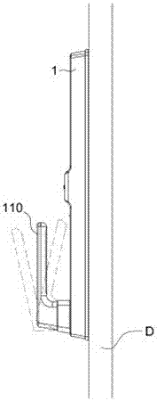
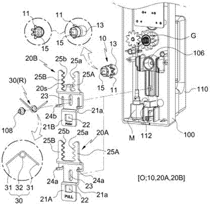
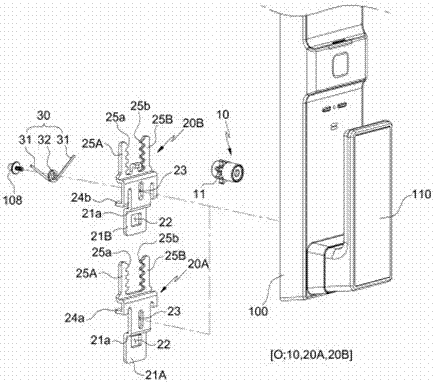
The invention discloses a door lock equipped with a pull-push handle. The present invention relates to a door lock which rotates a handle of the door lock forwards or backwards by pulling or pushing the handle forwards or backwards without horizontally rotating the handle of the door lock to input a latch bolt of the door lock to open a door. The door lock introduces a pinion having a sawtooth portion formed on an external circumference of one side thereof to install the handle by switching a pull-push direction of the handle to be matched with an open direction of the door; and first and second elevation racks in which corresponding sawtooth portions, which can be engaged with the sawtooth portion, are formed in an opposite direction to replace the first and second elevation racks when the door lock is coupled by changing a direction of the pinion to allow the sawtooth portion to face one side or the other side, thus switching a pull-push direction of the handle.

Description

technical field [0001] The present invention relates to a door lock. The present invention does not need to rotate the handle of the door lock left and right, but to turn the handle by pulling or pushing the handle of the door lock back and forth to introduce the latchbolt of the door lock, so that the door can be opened. The direction of opening the door is set by changing the push-pull direction of the handle. The door lock adopts a pinion and first and second lifting rails. The pinion has a gear part formed on one side of the outer peripheral surface. The first and second The corresponding gear parts of the two lifting rails that can be engaged with the gear parts are formed facing opposite directions, and in the state where the direction of the pinion gears is changed and combined with the gear parts facing one side or the other side, the first gear parts are alternately arranged. , The second lifting rail, so that the push-pull direction of the handle can be converted. ...

Claims


Application Information

Patent Timeline
Patent Type & Authority Applications(China)
IPC IPC(8): E05B3/00
CPCE05B3/00
Inventor 赵阳日
Owner INNO ELECTRIC INC
Why Eureka
Try Eureka