
Grinding roller and methods for pulling off a strap and shrinking a strap onto the shaft of the grinding roller

A technology of rollers and tires, applied in the direction of grain processing, etc., can solve complex problems and achieve the effect of effective cooling

Inactive Publication Date: 2017-09-26
KHD HUMBOLDT WEDAG GMBH
View PDF12 Cites 1 Cited by
  • Summary
  • Abstract
  • Description
  • Claims
  • Application Information

AI Technical Summary

Problems solved by technology

The aforementioned problems cannot be transferred to the system of radial cooling channels, since the peripheral surface there cannot be implemented as a shrink-fitable rim because of its segments and its cooling holes parallel to the axis. Cooling channels lead from one or more cooling channels in the center of the roll core to the circumference or surface of the core as suggested in DE 2536688 A1 for hot pressing briquettes
[0006] In contrast, the improved and complex cooling system for press rolls with tires in document WO 2014 / 012770 is also due to the cooling holes in the tires and the cooling holes from the center to the tires in the core. The radial inflow and outflow channels of the tire are not suitable for use in the process of thermally removing the tire and shrinking the tire

Method used


Image

  • Grinding roller and methods for pulling off a strap and shrinking a strap onto the shaft of the grinding roller
  • Grinding roller and methods for pulling off a strap and shrinking a strap onto the shaft of the grinding roller
  • Grinding roller and methods for pulling off a strap and shrinking a strap onto the shaft of the grinding roller

Examples


Embodiment Construction

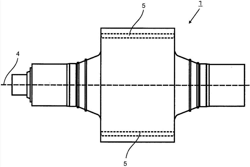
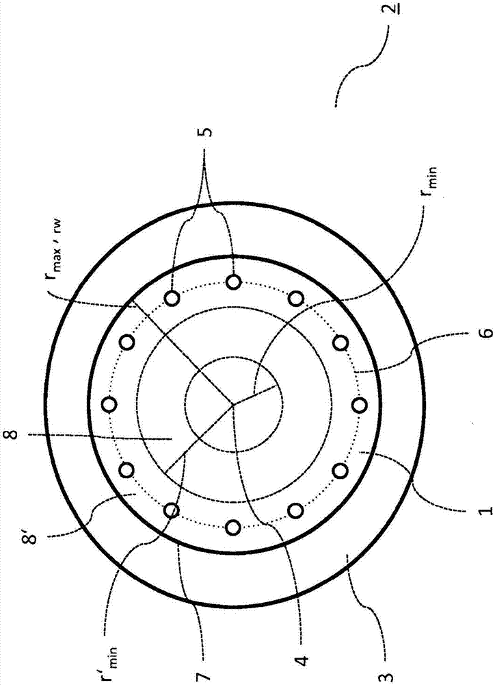
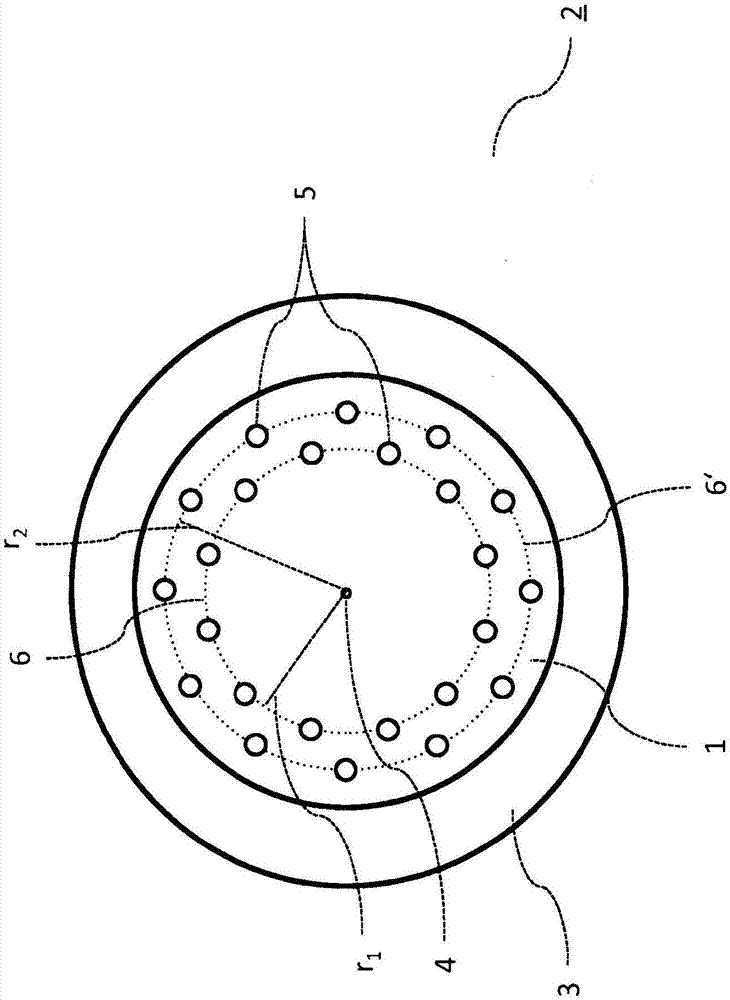
[0023] exist figure 1 The shaft 1 of a roll 2 according to the invention, which is typically used in high-pressure rolling machines (rollers), is shown in side view. The roller 2 comprises a shaft 1 and a wear-resistant web 3 , not shown here together, which is connected to the shaft 1 in a shrink-fit connection. The shaft 1 is mounted rotatably and rotationally symmetrically with respect to the axis of rotation 4 and tapers towards the ends for better support, lighter weight and easier mounting of the tire 3 from the center of the shaft 1 with the largest diameter Remove from the section and put the tire on the section. Furthermore, two cooling holes 5 arranged according to the invention in the outer region of the shaft 1 are shown schematically. The two cooling holes pass through the shaft 1 in the longitudinal direction and have open ends on both sides, so that when the tire 3 is shrunk onto the shaft 1 in the method according to the invention and is non-positively connec...


PUM


Abstract

The invention relates to a grinding roller (2) of a high-pressure roller press, comprising a shaft (1) and a wear-resistant strap (3), wherein the strap (3) is frictionally shrunk onto the shaft (1). The invention further relates to a method for separating a strap (3) and a shaft (1) in the case of such a grinding roller (2) and to a method for frictionally connecting a strap (3) and a shaft (1) in order to form such a grinding roller (2). According to the invention, the shaft (1) has a plurality of cooling bores (5) passing through in the axial direction for gaseous or liquid coolant to flow through said cooling bores, wherein the cooling bores (5) are arranged in the outer region of the shaft (1). Furthermore, in order to separate the strap (3) from the shaft (1), according to the invention, the strap (3) is heated by supplying heat from outside, the shaft (1) is simultaneously cooled by means of a coolant flowing through the cooling bores (5), and the strap (3) is pulled off from the shaft (1) in the longitudinal direction.

Description

technical field [0001] The invention relates to a roll of a high-pressure rolling machine, the roll comprising a shaft and at least one wear-resistant rim, wherein the shaft is rotationally symmetrical about an axis of rotation, wherein the shaft and the at least one The tires are coaxial with one another and are shrunk onto the shaft in a non-positive fit in the longitudinal section of the shaft. Furthermore, the invention relates to a method for separating tires and shafts in such rolls and a method for non-positively connecting tires and shafts to form such rolls, wherein the Wheel and shaft are designed with an interference fit in their diameters. Background technique [0002] Rollers are used as part of high-pressure roller compactors (roller compactors, material bed roller mills) to pulverize granular grinds (eg cement clinker). In this case, a roll nip is formed between two rollers, into which the ground material is introduced by means of the two counter-rotating ro...

Claims


Application Information

Patent Timeline
Patent Type & Authority Applications(China)
IPC IPC(8): B02C4/02B02C4/30
CPCB02C4/02B02C4/30B02C4/44
Inventor D·布伦德勒
Owner KHD HUMBOLDT WEDAG GMBH
Learn More