A state recognition method and device for a touch object
A state recognition and object technology, applied in the field of state recognition methods and devices for touch objects, can solve the problems of high cost, cumbersome operation, reduced user experience, etc., and achieve the effects of low cost and improved operation efficiency.
- Summary
- Abstract
- Description
- Claims
- Application Information
AI Technical Summary
Problems solved by technology
Method used
Image
Examples
Embodiment 1
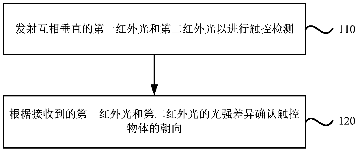
[0024] figure 1 It is a flow chart of a method for identifying the state of a touch object provided in Embodiment 1 of the present invention. This embodiment is applicable to the situation where the state of the touch object needs to be identified. This method can be implemented by the state recognition device of the touch object To perform, the device may be implemented by software and / or hardware. The method specifically includes the following steps:
[0025] Step 110 , emit the first infrared light and the second infrared light perpendicular to each other for touch detection.
[0026] Exemplarily, the first infrared light and the second infrared light perpendicular to each other can be emitted by infrared emitting tubes arranged in the horizontal direction and the vertical direction. For example, a circuit board frame is installed on the touch screen of a touch electronic device, and densely distributed infrared emitting tubes and infrared receiving tubes are installed on...
Embodiment 2
[0039] Figure 4 It is a flow chart of a method for identifying the state of a touch object provided in Embodiment 2 of the present invention. This embodiment is further optimized on the basis of the foregoing embodiments. The method provided in this embodiment specifically includes the following steps:
[0040] Step 310 , emit the first infrared light and the second infrared light perpendicular to each other for touch detection.
[0041] Step 320 , confirm the orientation of the touch object according to the intensity difference between the received first infrared light and the second infrared light.
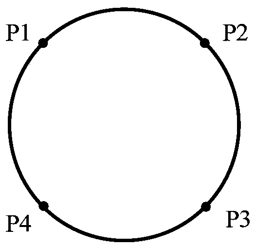
[0042] Wherein, the touch object includes a transparent pen tip, and two oppositely arranged first light-shielding strips and two oppositely arranged second light-shielding strips are arranged on the outside of the transparent pen head. The light transmittance of the first light-shielding strips and the second light-shielding strips are different.
[0043] Preferably, if the ...
Embodiment 3
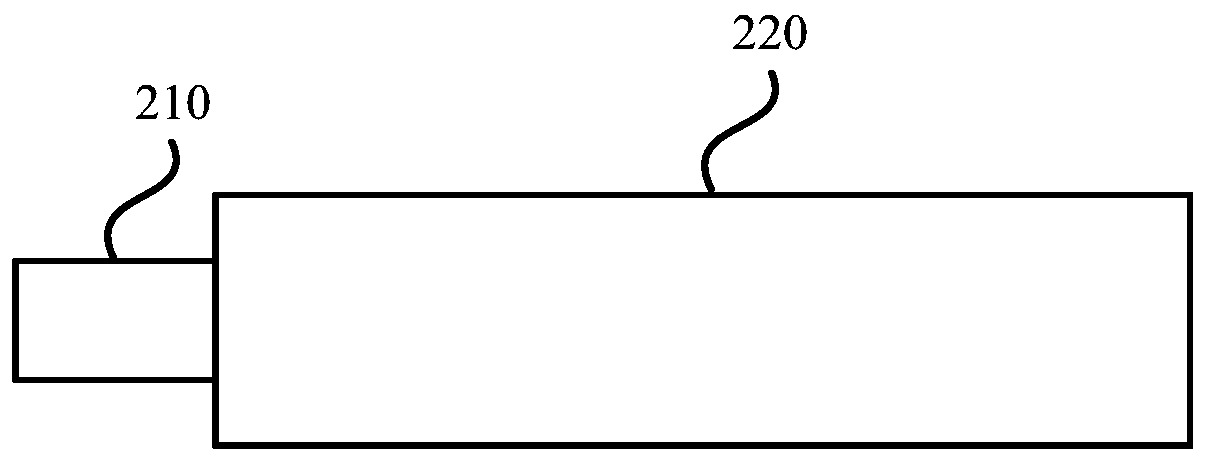
[0054] Figure 7 It is a schematic structural diagram of a state recognition device for a touch object provided in Embodiment 3 of the present invention. see Figure 7 , the device includes: a touch detection module 410 and an orientation confirmation module 420, wherein,
[0055] A touch detection module 410, configured to emit first infrared light and second infrared light perpendicular to each other for touch detection;
[0056] An orientation confirming module 420, configured to confirm the orientation of the touch object according to the received light intensity difference between the first infrared light and the second infrared light;
[0057] The touch object includes a transparent pen head, and two oppositely arranged first light-shielding strips and two oppositely arranged second light-shielding strips are arranged on the outside of the transparent pen head. Rates are different.
[0058] In the above solution, optionally, further comprising: a response confirmatio...
PUM
 Abstract
Description
Claims
Application Information
 - Generate Ideas
- Intellectual Property
- Life Sciences
- Materials
- Tech Scout
- Unparalleled Data Quality
- Higher Quality Content
- 60% Fewer Hallucinations
Browse by: Latest US Patents, China's latest patents, Technical Efficacy Thesaurus, Application Domain, Technology Topic, Popular Technical Reports.
© 2025 PatSnap. All rights reserved.Legal|Privacy policy|Modern Slavery Act Transparency Statement|Sitemap|About US| Contact US: help@patsnap.com


