
High-density, high-flow vertical ring lift parking unit and automatic parking system

A vertical ring, high-density technology, applied in the field of automatic parking lots or parking garages, can solve the problems of low space ratio of parking spaces, high cost of use, and inability to enter and exit vehicles in batches, and achieve high density and cost reduction.

Active Publication Date: 2020-01-07
庞怡
View PDF6 Cites 0 Cited by
  • Summary
  • Abstract
  • Description
  • Claims
  • Application Information

AI Technical Summary

Problems solved by technology

[0006] The present invention proposes a high-density, large-flow vertical ring-type lifting parking unit and an automatic parking system, which can use less lift equipment and solve the problem of high cost of using lifts in existing parking lots and low ratio of parking spaces to lift passages , unable to allow vehicles to enter and exit in batches, etc., so as to realize a low-cost, high-density, large-flow parking system

Method used


Image

  • High-density, high-flow vertical ring lift parking unit and automatic parking system
  • High-density, high-flow vertical ring lift parking unit and automatic parking system
  • High-density, high-flow vertical ring lift parking unit and automatic parking system

Examples


Embodiment 1

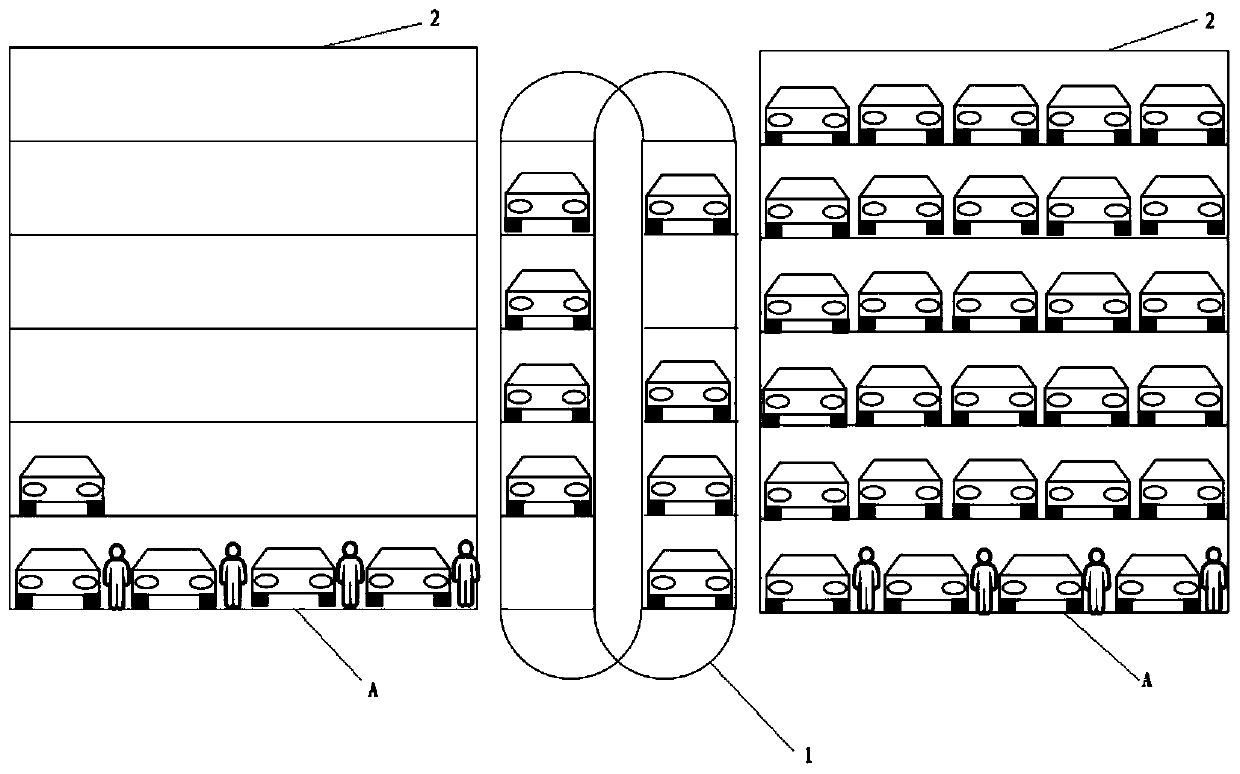
[0039] Such as figure 1 As shown, the lift can also be said to be a parking unit that can move vertically up and down, including multiple vehicle-carrying platforms. The vehicle-carrying platform is supported and guided by "double ring" rails. Optionally, a third rail is available for chain driven platforms. The lift footprint is about the size of two parking spaces. It can also be used as a "vertical" car park by itself, but even better as a quick lift in a multi-storey garage with more space, less cost, and more robustness. This is more in line with the design principle of "performing their own duties".

Embodiment 2

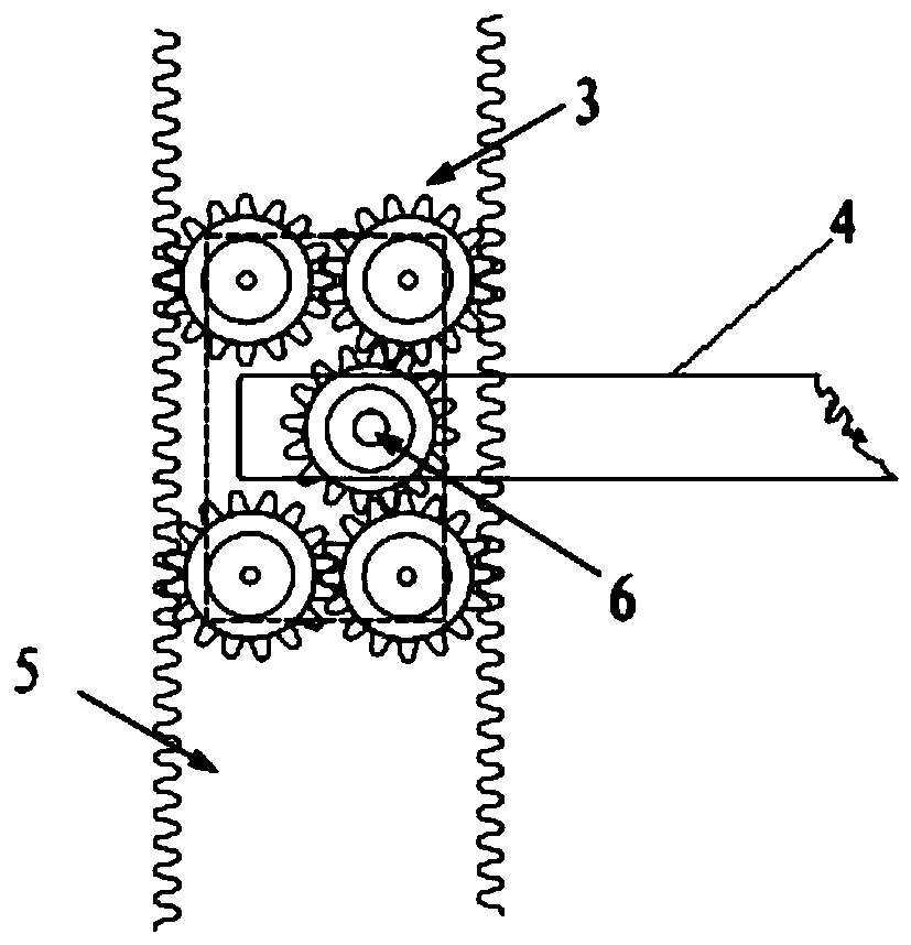
[0041] Such as figure 2 As shown, an elevator of the present invention has "double ring" grooved guide rails at both ends, which are used to support the vehicle platform and make it run along the vertical loop. The rail slots have teeth on the inside sides that engage the platform's gearing. Each platform has four gear units mounted at its four corners. Each gear unit has a plurality of gears, and the gear unit itself can rotate about a support shaft extending from the platform. A gear unit driven by a motor moves the platform along the rails. The four gears of the platform are mechanically connected to make them move at the same speed.

Embodiment 3

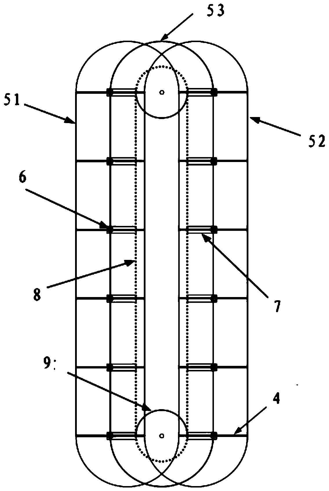
[0043] Such as image 3 Shown, the present invention can have the 3rd guide rail to be used for the operation of chain-driven vehicle-carrying platform. There is a support shaft in the middle between the gears at the two ends of the vehicle-carrying platform. The supporting shaft is connected with the driving chain through a connecting rod. The function of the connecting rod is to ensure the distance between the platforms, especially when the platform moves in a circle at the upper and lower ends of the elevator. The chain is driven by a motor from one of the upper and lower sprockets connected to it. The gearing of such a platform does not require a motor drive.

[0044] With the chain-driven third guide rail, the distance between the vehicle-carrying platforms is mechanically fixed, reliable and unchangeable. Without this third rail, the platform spacing is controlled by a software program and is variable. This variability is sometimes useful, such as enabling the vehic...


PUM


Abstract

The present invention discloses a vertical ring type parking unit and a high density and high flow automatic parking system including one or more vertical ring lift parking units as lifts and a solid parking lot on one or both sides. Said elevator is a vertical parking unit which is vertically movable up and down, and a plurality of carrier platforms are arranged vertically, and the platform of the lift is running along an annular guide rail.The invention has the advantages of high density and high flow advantages, and can quickly put or release the vehicle in parallel and 'pipeline' way. The vehicle can be parked in the proper position without human intervention, and only one lifter can be realized high-density large flow of parking, most of the parts are also easy to get the standardization of industrial products.

Description

technical field [0001] The invention relates to an automatic parking lot or a parking garage, and more particularly to a high-density, high-flow automatic parking system. Background technique [0002] Lifting and traversing parking equipment adopts a vehicle-carrying plate to lift or traversing to access vehicles. Generally, it is a quasi-unmanned mode, that is, a way for people to move the car after leaving the equipment. According to the arrangement of parking spaces: [0003] 1) Arrangement on the whole ground: there are two floors, three floors, four floors, five floors, generally no more than five floors, but more than seven floors, and some have reached 18 floors, but compared with the lower floors, the lifting speed must be increased to ensure Customer usage requirements. 2) Semi-underground layout: This layout can build more parking spaces than the whole ground layout, and the space utilization rate is high, but the civil construction investment is large. 3) Repea...

Claims


Application Information

Patent Timeline
Patent Type & Authority Patents(China)
IPC IPC(8): E04H6/18E04H6/22
CPCE04H6/187E04H6/22
Inventor 庞怡
Owner 庞怡
Learn More