


Quick Research
Generate reliable direction feasibility study reports for your R&D in just a few steps.

Technical Q&A
Discover and master advanced knowledge NOW. Basics, ideas, possibilities, all at once.

Find Solutions
As an expert in R&D theories, this can generate solutions to your technical problems instantly.

Evaluate Feasibility
Analyze your overall solution with one click, know your potential R&D risks in advance.

Monitor Landscape
Get weekly tech updates, stay abreast of the latest tech innovations and key insights.
Rotary Traveling Wave Oscillator Circuit
A technology for converter circuits and oscillators, which is applied in the direction of power oscillators, circuits, analog-to-digital converters, etc., and can solve problems such as the difficulty of coupling oscillator phase offsets
- Summary
- Abstract
- Description
- Claims
- Application Information
AI Technical Summary
Problems solved by technology
Method used
Image


Examples
Embodiment Construction
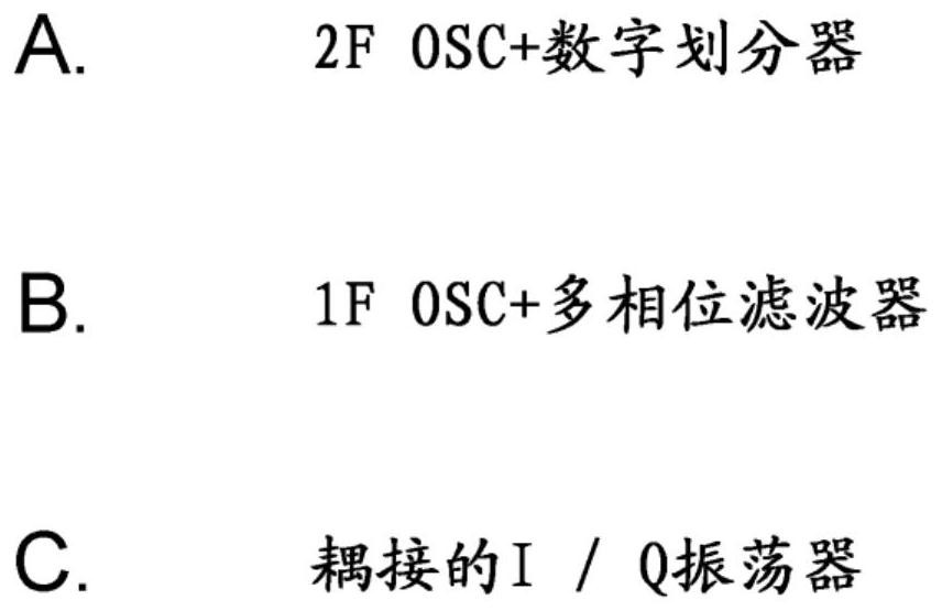
[0040] The present inventors have studied corresponding to figure 1 Circuits of methods A, B and C. However, they have identified the rather distant Rotary Traveling Wave Oscillator (RTWO) as suitable for quadrature signal generation considering the ADC and DAC circuits described above.
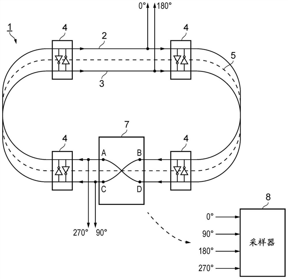
[0041] figure 2 is a schematic diagram of an example RTWO 1 for generating quadrature phase signals. RTWO 1 includes paired signal lines 2 and 3 and a plurality of regeneration elements 4 .
[0042] Signal line 2 has ends A and B and signal line 3 has ends C and D. Signal lines 2 and 3 are connected end-to-end with end B connected to end C and end D connected to end A to form a closed or endless loop of signal lines. It should be understood that such signal lines may be implemented as (ideal, lossless) transmission lines, and the present disclosure will be understood accordingly.
[0043] Note that the pair of signal lines 2 and 3 generally follow path 5 which itself forms an endless lo...
PUM
 Abstract
Description
Claims
Application Information
 - R&D Engineer
- R&D Manager
- IP Professional
- Industry Leading Data Capabilities
- Powerful AI technology
- Patent DNA Extraction
Browse by: Latest US Patents, China's latest patents, Technical Efficacy Thesaurus, Application Domain, Technology Topic, Popular Technical Reports.
© 2024 PatSnap. All rights reserved.Legal|Privacy policy|Modern Slavery Act Transparency Statement|Sitemap|About US| Contact US: help@patsnap.com