Cold water recycling device, shower system and cold water recycling method

A technology of cold water recovery and water inlet valve, applied in heating devices, solar thermal devices, lighting and heating equipment, etc., can solve the problems of space occupation, product cost increase, waste, etc., to achieve convenient temperature adjustment, stable water supply capacity, The effect of saving energy

Inactive Publication Date: 2017-09-19
北京凌顶科技有限公司
View PDF5 Cites 0 Cited by
  • Summary
  • Abstract
  • Description
  • Claims
  • Application Information

AI Technical Summary

Problems solved by technology

[0003] 1. There is no cold water recovery device. Generally, there are two options for users to operate. a. Directly drain the cold water, causing waste
bUse other containers to store this part of cold water for other purposes. The storage not only occupies a certain space, but also brings a lot of extra operations to the user during the collection process, and the user experience is poor.
[0004] 2. The cold water recovery is adopted, and external power is used to utilize this part of the cold water in the bathing process. Although the operation of collecting and storing cold water is omitted, an additional power device is required, which not only increases the product cost but also is not conducive to energy saving.
The constant pressure provided by the external power unit will also lead to large differences in the pressure difference between cold and hot water at different users, which is not conducive to the constant temperature system to adjust the constant temperature, or even cannot adjust the constant temperature state, and the water supply pressure is unstable

Method used


Image

  • Cold water recycling device, shower system and cold water recycling method

Examples


Embodiment 1

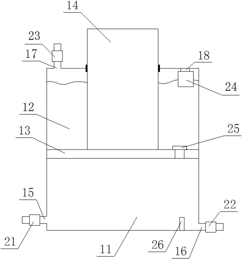
[0034] figure 1 It is a schematic structural view of the cold water recovery and reuse device of Embodiment 1 of the present invention; in the figure, the meanings indicated by each reference numeral are as follows; 11, the first cavity; 12, the second cavity; 13, the sliding piston; 14, the sliding piston rod ;15, the first water inlet; 16, the first water outlet; 17, the second water inlet; 18, the exhaust port; 21, the first water inlet valve; 22, the first water outlet valve; 23, the second water inlet valve ; 24, exhaust valve; 25, connecting valve; 26, position switch.

[0035] A cold water recovery and reuse device, including a cavity, a sliding piston 13 is arranged in the cavity, the sliding piston is connected with a sliding piston rod 14, and the density of the assembly composed of the sliding piston and the sliding piston rod is much smaller than that of water, for example, the overall Density can be 0.3 times of water density, sliding piston 13 is fixedly connect...

Embodiment 2

[0058] A shower system is provided with any one of the above-mentioned cold water recovery and reuse devices.

[0059] The shower system also has the corresponding technical effect of the above-mentioned cold water recovery and reuse device.


PUM


Abstract

The invention relates to a cold water recycling device, a shower system with the cold water recycling device and a cold water recycling method. The cold water recycling device comprises a cavity. A sliding piston is arranged in the cavity and is further connected with a sliding piston rod. The density of an assembly formed by the sliding piston and the sliding piston rod is smaller than that of water. The sliding piston is connected with the cavity in sliding and sealing modes and further divides the cavity into a first cavity body and a second cavity body. A first water inlet and a first water outlet are formed in the first cavity body. A second water inlet and an exhaust outlet are formed in the second cavity body. The first water inlet is provided with a first water inlet valve, and the first water outlet is provided with a first water outlet valve. The second water inlet is provided with a second water inlet valve, and the exhaust outlet is provided with an exhaust valve. The exhaust outlet is located in the top of the second cavity body. The sliding piston is provided with a communicating valve used for communicating the first cavity body. According to the cold water recycling device, cold water recycling can be achieved automatically and energy consumption is small.

Description

technical field [0001] The invention belongs to the technical field of water heater control devices, and in particular relates to a cold water recovery and reuse device, a shower system and a cold water recovery and reuse method. Background technique [0002] In the shower system, since the shower hot water source and the water outlet are generally far away, there is more cold water in the hot water pipeline, and more cold water needs to be drained at the beginning of each shower. In the prior art, there are several solutions as follows: [0003] 1. There is no cold water recovery device, and there are two options for general users to operate, a. Directly drain the cold water, resulting in waste. b Use other containers to store this part of cold water for other purposes. The storage not only occupies a certain space, but also brings a lot of extra operations to the user during the collection process, and the user experience is poor. [0004] 2. The cold water recovery is a...

Claims


Application Information

Patent Timeline
Patent Type & Authority Applications(China)
IPC IPC(8): F24H9/00F24H9/20F24J2/46F24J2/40
CPCF24H9/0005F24H9/2007
Inventor 张洪宝
Owner 北京凌顶科技有限公司
Why Eureka
Try Eureka