
Large line width CO-OFDM phase noise compensation method of time-frequency domain Kalman filtering

A phase noise compensation, CO-OFDM technology, applied in the field of phase noise compensation of large linewidth CO-OFDM systems, can solve problems such as difficulty in improving estimation accuracy, modulation of CO-OFDM systems, and limited improvement range.

Active Publication Date: 2017-09-15
ZHEJIANG UNIV OF TECH
View PDF3 Cites 23 Cited by
  • Summary
  • Abstract
  • Description
  • Claims
  • Application Information

AI Technical Summary

Problems solved by technology

However, if one wants to continue to improve the tolerance to the laser linewidth, the improvement range is very limited at the cost of sacrificing the complexity of the algorithm, which shows that the LS estimation is difficult to improve the estimation accuracy under the condition of large linewidth (Reference 5, Ren Hongliang, Kang Shaoyuan, Lu Jin, Guo Shuqin, Qin Yali, Hu Weiwei, Research on Blind Phase Noise Compensation Algorithm in CO-OFDM System with Large Linewidth. Acta Optics Sinica, 2017, 37(01):0106005.)
For the Wiener process model of laser phase noise, some researchers proposed a CO-OFDM phase noise compensation algorithm based on Kalman filtering, but it did not address the large linewidth and high-order modulation CO-OFDM system (Reference 6, Li Lingxiang, Li Jibi. A third-order phase noise compensation algorithm based on Kalman filter in CO-OFDM system. Optoelectronics Laser, 2016(10):1047-1053.)

Method used


Image

  • Large line width CO-OFDM phase noise compensation method of time-frequency domain Kalman filtering
  • Large line width CO-OFDM phase noise compensation method of time-frequency domain Kalman filtering
  • Large line width CO-OFDM phase noise compensation method of time-frequency domain Kalman filtering

Examples

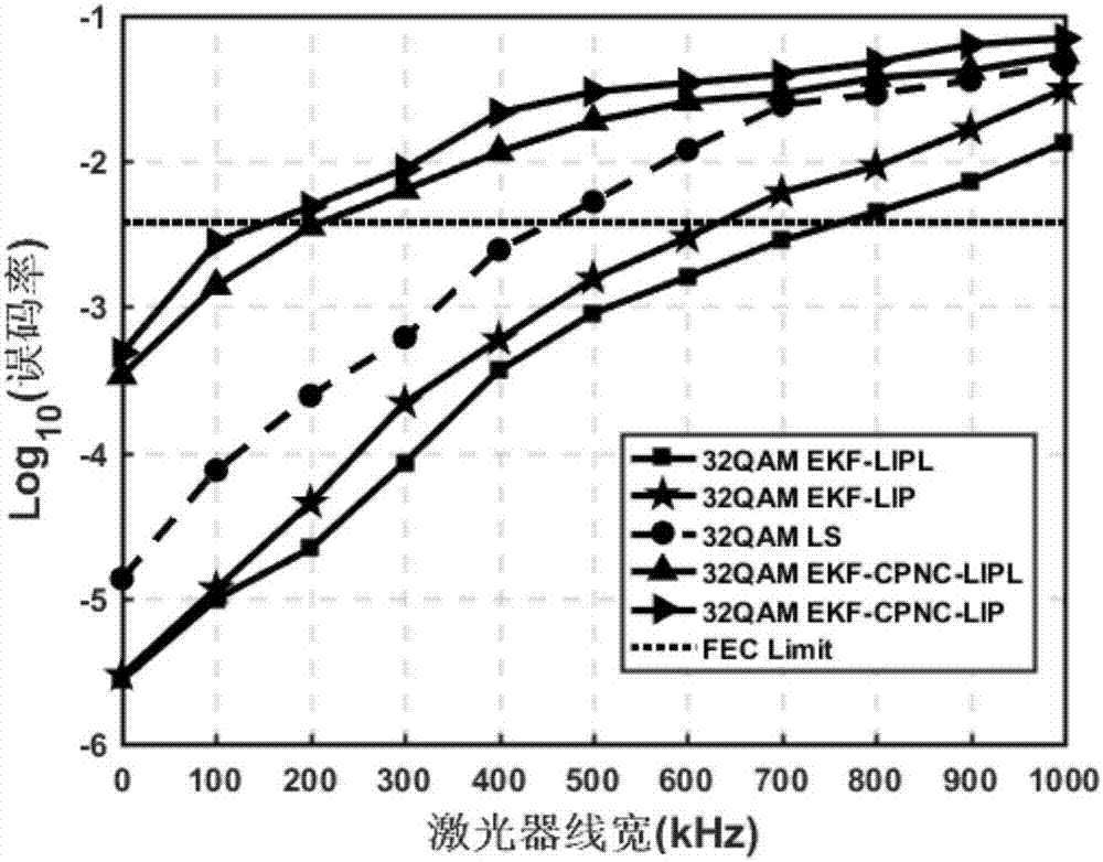

Embodiment Construction

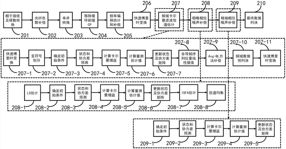
[0129] The present invention will be described in further detail below in conjunction with the embodiments and the accompanying drawings, but the embodiments of the present invention are not limited thereto.

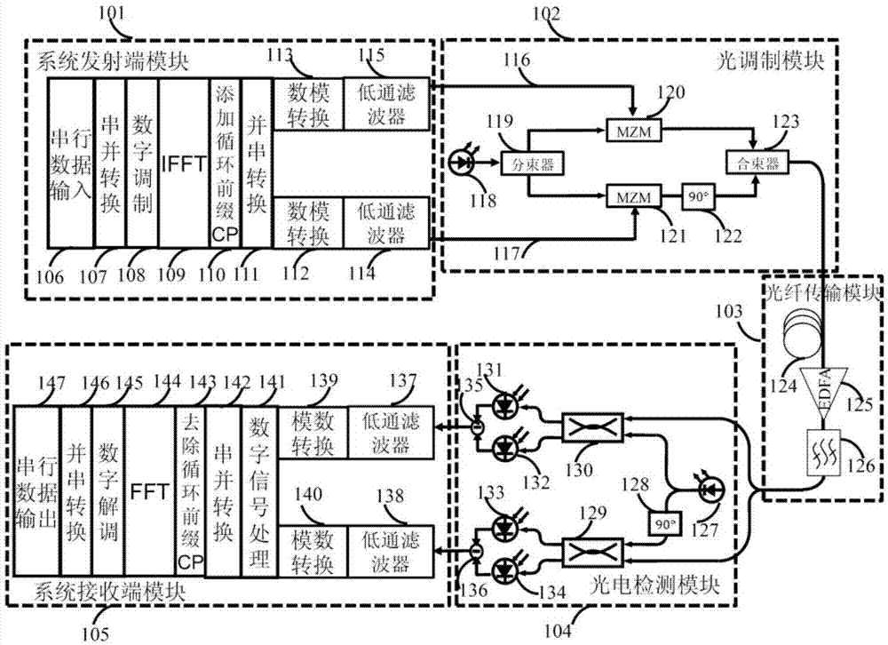
[0130] refer to Figure 2 to Figure 9 , a large-linewidth CO-OFDM phase noise compensation method based on time-frequency domain Kalman filtering, mainly related to the signal processing problem at the receiving end of a coherent optical orthogonal frequency division multiplexing CO-OFDM system, referring to the CO-OFDM system in the background technology A detailed description of the structure.

[0131] Such as figure 1As shown, the CO-OFDM system includes a CO-OFDM system transmitter module 101, a CO-OFDM optical modulation module 102, an optical fiber transmission module 103, a photoelectric detection module 104, and a CO-OFDM system receiver module 105. The signal generated by the system transmitter The up-conversion of optical modulation becomes the CO-OFDM signal...


PUM


Abstract

The invention provides a large line width CO-OFDM phase noise compensation method of time-frequency domain Kalman filtering. The method comprises the following steps: firstly, performing Kalman filtering on receiving end training symbol data in the frequency domain, and performing channel equalization, then dividing each OFDM symbol into a plurality of sub-symbols, performing time domain extended Kalman filtering at a pilot frequency sequence in each sub-symbol to obtain a rough phase noise estimation value of each time domain sampling point, and compensating the rough phase noise estimation value; performing linear interpolation between the rough phase noise estimation values at the last pilot frequency sequence of the adjacent sub-symbol to obtain the rough phase noise estimation value of each time domain sampling point, compensating the rough phase noise estimation value, and performing pre- judgment after performing phase noise compensation by using the Avg-BL method; and finally converting the frequency domain data into the time domain to combine with the initial time domain data after the pre- judgment, performing extended Kalman filtering at each sampling point to calculate a precise phase noise estimation value, and compensating the precise phase noise estimation value. The large line width CO-OFDM phase noise compensation method has the advantages of better phase noise equalization effect, good compensation effect and small calculation complexity.

Description

technical field [0001] The invention belongs to the technical field of optical communication networks, and in particular relates to a phase noise compensation method of a CO-OFDM system with a large line width. Background technique [0002] Coherent optical OFDM system Orthogonal Frequency Division Multiplexing (CO-OFDM) technology has a good suppression effect on fiber dispersion and polarization mode dispersion, the ability to flexibly compensate system damage by digital signal processing, high frequency spectrum With advantages such as utilization rate, it has become one of the technologies that have attracted much attention in the fields of long-distance high-speed communication systems and optical access networks. [0003] CO-OFDM system structure such as figure 1 As shown, it can be divided into five modules according to their functions: CO-OFDM system transmitter module 101, optical modulation module 102, optical fiber transmission module 103, photoelectric detection...

Claims


Application Information

Patent Timeline
IPC IPC(8): H04B10/61H04B10/2513
CPCH04B10/2513H04B10/6165
Inventor 唐英杰董月军卢瑾任宏亮乐孜纯
Owner ZHEJIANG UNIV OF TECH
Learn More