
Wireless charger and charging control method thereof

A charging control method and wireless charger technology, applied in current collectors, battery circuit devices, electric vehicles, etc., can solve problems such as difficulty in matching a variety of different devices to be charged, trouble, and impact on use, so as to improve usability and user The effect of experience

Inactive Publication Date: 2017-09-15
里程
View PDF6 Cites 5 Cited by
  • Summary
  • Abstract
  • Description
  • Claims
  • Application Information

AI Technical Summary

Problems solved by technology

[0003] In the process of realizing the present invention, the inventor found the following problems in the current technology: accurate alignment is required between the sending coil of the wireless charger and the receiving coil of the device to be charged in the existing Qi standard, and inaccurate alignment will lead to charging Low efficiency, affecting use
At this stage, since the coil of the wireless charger is fixed, it is usually used to mark the charging position on the wireless charger to remind the user to place the device to be charged. This is not only troublesome, but also due to the variety of devices to be charged, the wireless charger It is difficult to match a variety of different devices to be charged, and the user experience is poor

Method used


Image

  • Wireless charger and charging control method thereof
  • Wireless charger and charging control method thereof
  • Wireless charger and charging control method thereof

Examples


no. 1 example

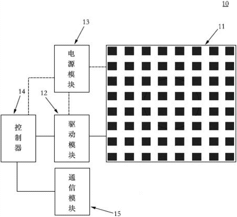
[0039] Such as figure 1 As shown, the first embodiment of the present invention provides a wireless charger. The wireless charger 10 includes a metal dot matrix 11 electrically connected to a power module 13, a driving module 12 and a controller 14. The wireless charger may be in the form of a wireless charging board, or may be embedded in other devices, such as embedded in a desktop or embedded in a car shelf, which is not limited in the embodiment of the present invention.

[0040] In this embodiment, the power supply module 13 can be a fixed power supply or a mobile power supply.

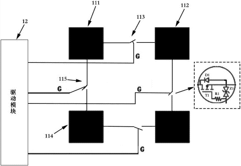
[0041] Please combine figure 2 As shown, in this embodiment, the metal dot matrix 11 includes a plurality of metal points (111, 112, 114 in the accompanying drawing), and the adjacent metal dots in the metal dot matrix 11 pass through the controllable switch (the accompanying drawing 113, 115) are connected, and the control end of the controllable switch (113, 115 in the accompanying drawings)...

no. 2 example

[0085] The second embodiment of the present invention provides a charging control method of a wireless charger, the method includes the steps of:

[0086] The power module powers on the wireless charger;

[0087] The controller generates a first control signal to the drive module;

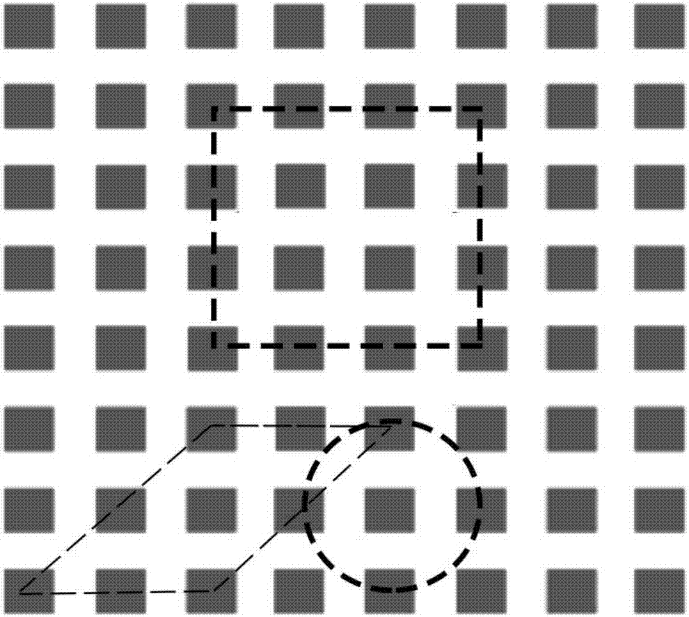
[0088] According to the first control signal generated by the controller, the driving module drives the controllable switches in the first area of ​​the metal dot matrix to be turned on, so that the metal points in the first area of ​​the metal dot matrix are connected to form the first emission A coil, the first transmitting coil can generate an induced magnetic field in a energized state.

[0089] In one embodiment, the method also includes the steps of:

[0090] The controller obtains the charging efficiency of the device to be charged through the communication module, and judges whether the charging efficiency of the device to be charged meets a preset value; if the charging efficiency of the...


PUM


Abstract

The invention discloses a wireless charger and a charging control method thereof. The wireless charger comprises a metal lattice, a driving module and a controller, wherein the metal lattice, the driving module and the controller are electrically connected with a power supply module. The metal lattice comprises a plurality of metal points. Adjacent metal points in the metal lattice are connected through a controllable switch. The control end of the controllable switch is connected with the driving module. The controller generates a first control signal to the driving module. The driving module drives the controllable switches in a first area of the metal lattice according to the first control signal for realizing conduction so that the metal points in the first area of the metal lattice are started for forming a first transmitting coil. According to the wireless charger and the charging control method thereof, through forming the coil by means of connecting the plurality of metal points and adjusting the controllable switches, charging coil position adjustment can be realized, thereby realizing free placement of to-be-charged equipment in the wireless charger, realizing high suitability for different kinds of to-be-charged equipment, and improving wireless charging availability and user experience.

Description

technical field [0001] The invention relates to the technical field of wireless charging, in particular to a wireless charger and a charging control method thereof. Background technique [0002] Wireless charging technology is a technology that uses magnetic resonance to transmit charges in the air between the charger and electronic products, and coils and capacitors form resonance between the charger and electronic products to achieve efficient power transmission. At present, the methods that can realize this technology include the electromagnetic induction coupling method of the Qi standard, the radio wave method, and the electromagnetic resonance method proposed by MIT (Massachusetts Institute of Technology). [0003] In the process of realizing the present invention, the inventors found the following problems in the current technology: accurate alignment is required between the sending coil of the wireless charger and the receiving coil of the device to be charged in the...

Claims


Application Information

Patent Timeline
Patent Type & Authority Applications(China)
IPC IPC(8): H02J7/00H02J50/40
CPCH02J7/0013H02J50/40
Inventor 里程
Owner 里程
Learn More