Conveying type carrying vehicle
A technology of moving vehicles and conveying rollers, which is applied in the field of transportation, can solve the problems of lack of versatility and high transformation costs, and achieve the effect of reducing construction costs and improving the efficiency of loading and unloading operations
- Summary
- Abstract
- Description
- Claims
- Application Information
AI Technical Summary
Problems solved by technology
Method used
Image
Examples
Embodiment 1
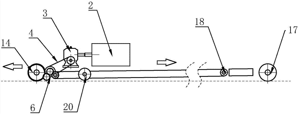
[0058] Such as Figure 1-2 As shown, a transmission type truck of the present invention includes an active transmission device and a driven transmission device, the active transmission device and the driven transmission device are connected through a transmission shaft 10, and the active transmission device and the driven transmission device are installed on the transmission table the front of 1;
[0059] It also includes a front drive wheel assembly 14 and a rear drive wheel assembly 17, the front drive wheel assembly 14 is located at the two ends of the front portion of the transmission platform 1, and the rear drive wheel assembly 17 is respectively installed at the two ends of the rear portion of the transmission platform 1. The front drive wheel assembly 14 and the rear drive wheel assembly 17 are all in contact with the ground, so that the truck can move forward and backward;
[0060] The active transmission device includes a power source 2, a speed reducer 3, a first p...
Embodiment 2
[0068] The difference between this embodiment and Embodiment 1 is that the rear drive wheel assembly 17 is provided with a drive motor to control its motion, and the second sprocket transmission assembly is omitted, that is, the rear drive wheel assembly 17 is an independent running assembly, which is driven by The control of the motor to the rear drive wheel assembly 17 makes it consistent with the speed of the front drive wheel assembly 14 and the direction of travel.
Embodiment 3
[0070] The difference between this embodiment and Embodiment 1 is that: a transmission type transport vehicle includes a transmission device symmetrically installed on the front of the transmission table 4', the transmission device includes a first transmission roller 3', the first transmission roller 3' One end is provided with gear 2 ', and the first conveying roller 3 ' is provided with conveying belt 5 ', and the end of conveying belt 5 ' away from the first conveying roller 3 ' is provided with the second conveying roller 6 ', and the first conveying roller 3 ' and the first conveying roller 3 ' Two conveying rollers 6' are arranged side by side;
[0071] Also comprise front drive wheel assembly 1 ', front drive wheel assembly 1 ' is installed on the side of first transmission roller 3 ' and meshes with gear 2 ', is provided with the front drive motor that controls its motion in front drive wheel assembly 1 '.
[0072] It also includes a rear drive wheel assembly 7', the ...
PUM
 Abstract
Description
Claims
Application Information
 - Generate Ideas
- Intellectual Property
- Life Sciences
- Materials
- Tech Scout
- Unparalleled Data Quality
- Higher Quality Content
- 60% Fewer Hallucinations
Browse by: Latest US Patents, China's latest patents, Technical Efficacy Thesaurus, Application Domain, Technology Topic, Popular Technical Reports.
© 2025 PatSnap. All rights reserved.Legal|Privacy policy|Modern Slavery Act Transparency Statement|Sitemap|About US| Contact US: help@patsnap.com


