Polisher capable of adjusting polishing height of lipping of rail head

An adjustable grinding machine technology, applied in the direction of track, laying track, track maintenance, etc., can solve the problem that the relative position of the grinding wheel and the rail fat edge cannot be adjusted up and down, the overall grinding effect of the rail fat edge cannot be guaranteed, and the grinding of the rail fat edge cannot be guaranteed. Overall effect and other issues, to achieve the effect of improving swing flexibility, improving overall effect, and preventing falling

Pending Publication Date: 2017-09-15
西藏天仁科技发展有限公司
View PDF10 Cites 2 Cited by
  • Summary
  • Abstract
  • Description
  • Claims
  • Application Information

AI Technical Summary

Problems solved by technology

[0006] 1. The grinding wheel for grinding the rail is fed by screw screw, and the grinding amount is adjusted manually. The grinding wheel is only ground in the longitudinal or horizontal direction of the rail. There is only one grinding direction. The relative position between the grinding wheel and the fat edge of the rail cannot be adjusted. The height of the grinding position is relatively fixed, which affects the overall effect of rail fat edge grinding
[0007] 2. The walking device of the grinding machine is manually pushed through the walking wheels. The speed of manual pushing varies from fast to slow, and the speed of pushing is uneven. Changes in the speed of pushing will directly affect the quality of grinding, and the overall grinding effect of the fat edge of the rail cannot be guaranteed.

Method used


Image

  • Polisher capable of adjusting polishing height of lipping of rail head
  • Polisher capable of adjusting polishing height of lipping of rail head
  • Polisher capable of adjusting polishing height of lipping of rail head

Examples


Embodiment 1

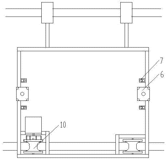
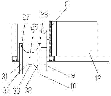
[0046] A grinding machine that can adjust the grinding height of the fat edge of the rail, including a frame 1, and also includes a vertical moving device and a walking device, and the vertical moving device includes a hanger 2, a ball bearing seat 3, a ball screw 4 and a ball mounted on a The ball nut 5 on the screw rod 4, the frame 1 is provided with a stepping motor 6 and an upper and lower slider 7, the hanger 2 is slidably connected with the frame 1 through the upper and lower sliders 7, the motor shaft of the stepping motor 6 and the ball bearing The seat 3 is connected, one end of the ball screw 4 is connected with the ball bearing seat 3, and the other end runs through the hanger 2, and the hanger 2 is connected with the ball screw 4 through the ball nut 5; Driven gear 9, travel wheel 10, roller 11 and the motor 12 that is arranged on the frame 1, drive gear 8 is connected with the motor shaft of motor 12, and driven gear 9 and drive gear 8 pass through gear engagement ...

Embodiment 2

[0049] A grinding machine that can adjust the grinding height of the fat edge of the rail, including a frame 1, and also includes a vertical moving device and a walking device, and the vertical moving device includes a hanger 2, a ball bearing seat 3, a ball screw 4 and a ball mounted on a The ball nut 5 on the screw rod 4, the frame 1 is provided with a stepping motor 6 and an upper and lower slider 7, the hanger 2 is slidably connected with the frame 1 through the upper and lower sliders 7, the motor shaft of the stepping motor 6 and the ball bearing The seat 3 is connected, one end of the ball screw 4 is connected with the ball bearing seat 3, and the other end runs through the hanger 2, and the hanger 2 is connected with the ball screw 4 through the ball nut 5; Driven gear 9, travel wheel 10, roller 11 and the motor 12 that is arranged on the frame 1, drive gear 8 is connected with the motor shaft of motor 12, and driven gear 9 and drive gear 8 pass through gear engagement ...

Embodiment 3

[0057] A grinding machine that can adjust the grinding height of the fat edge of the rail, including a frame 1, and also includes a vertical moving device and a walking device, and the vertical moving device includes a hanger 2, a ball bearing seat 3, a ball screw 4 and a ball mounted on a The ball nut 5 on the screw rod 4, the frame 1 is provided with a stepping motor 6 and an upper and lower slider 7, the hanger 2 is slidably connected with the frame 1 through the upper and lower sliders 7, the motor shaft of the stepping motor 6 and the ball bearing The seat 3 is connected, one end of the ball screw 4 is connected with the ball bearing seat 3, and the other end runs through the hanger 2, and the hanger 2 is connected with the ball screw 4 through the ball nut 5; Driven gear 9, travel wheel 10, roller 11 and the motor 12 that is arranged on the frame 1, drive gear 8 is connected with the motor shaft of motor 12, and driven gear 9 and drive gear 8 pass through gear engagement ...


PUM


Abstract

The invention discloses a polisher capable of adjusting the polishing height of lipping of rail head, and belongs to the technical field of railway maintenance equipment. The polisher comprises a rack. The polisher is characterized by further comprising a vertically moving device and a travelling device; the vertically moving device comprises a hanging bracket, ball bearing bases, ball screws and ball nuts, stepper motors and vertically sliding blocks are arranged on the rack, and the hanging bracket is connected with the rack in a sliding mode through the vertically sliding blocks; the travelling device comprises a driving gear, a driven gear, a travelling wheel, a rolling wheel and a motor, wherein the driving gear is connected with the motor shaft of the motor, the driven gear is driven by the driving gear through gear meshing, and the travelling wheel is connected with the driven gear. According to the polisher capable of adjusting the polishing height of the lipping of the rail head, when polishing is conducted on the lipping of the rail head, the polisher can uniformly move at a low speed, and a grinding wheel is driven to automatically feed in the vertical direction, so that polishing in the vertical direction is conducted on the lipping of the rail head, and the polishing speed is uniform; moreover, the grinding wheel can vertically move, and polishing is conducted on any position of the height of the lipping of the rail head, so that the overall effect of polishing of the lipping of the rail head is improved.

Description

technical field [0001] The invention relates to the technical field of railway maintenance equipment, in particular to a grinding machine capable of adjusting the grinding height of rail fat edges. Background technique [0002] At present, the rail grinding and repairing machines used in various works mainly include the French Gisma internal combustion rail grinding machine model MP12, the German Nobel internal combustion rail profiling grinding machine ROBEL13.44, the NC straight 5 type produced in Zhengzhou Luyuan, and the GM produced in Shandong. -4 type, internal combustion turnout grinding machine NCM-4.0 type produced in Jinzhou, NCM-4.9 type produced by Kunming Aotong, etc. The above rail grinding machines are mainly divided into two categories, rail surface grinding machines and turnout grinding machines. [0003] Rail surface grinding machine, take the GM-4 type produced in Shandong as an example. The GM-4 type grinding machine is mainly composed of main components...

Claims


Application Information

Patent Timeline
IPC IPC(8): E01B31/17
CPCE01B31/17
Inventor 徐旺
Owner 西藏天仁科技发展有限公司
Why Eureka
Try Eureka