Material rack mechanism achieving automatic guiding and locking

An automatic guiding and locking mechanism technology, applied in tool storage devices, manufacturing tools, etc., can solve problems such as inapplicability of small-scale processing, long refueling time, and long machine downtime, so as to reduce the difficulty of placement and reduce the Effects of downtime and shortened refueling time

Active Publication Date: 2017-09-15
西安精雕软件科技有限公司
View PDF5 Cites 1 Cited by
  • Summary
  • Abstract
  • Description
  • Claims
  • Application Information

AI Technical Summary

Problems solved by technology

This scheme has the characteristics of simple structure and stable operation, but at the same time, its shortcomings are quite obvious.
First of all, it takes a long time for loading and unloading workpieces, and the machine tool stops for a long time, which reduces the processing efficiency of the processing unit; secondly, it is inconvenient to change the types of workpieces, and it is difficult to adapt to the processing requirements of various varieties.
[0004] Disc or ring silos for small workpieces, mainly for small disc or rod-shaped parts, cannot meet the storage requirements of larger workpieces
However, large storage silos are expensive and are not suitable for small-scale processing. They are generally used as storage for multi-variety fixtures.
However, the commonly used fixed silo has long refueling time, long machine downtime, and inconvenient replacement of workpiece types. Various factors lead to a great reduction in the processing efficiency of the automated processing unit.

Method used


Image

  • Material rack mechanism achieving automatic guiding and locking
  • Material rack mechanism achieving automatic guiding and locking
  • Material rack mechanism achieving automatic guiding and locking

Examples


Embodiment Construction

[0030] In the description of the present invention, it should be understood that the orientation or positional relationship indicated by the terms "upper", "lower", "left", "right", "horizontal" etc. is based on the orientation or positional relationship shown in the drawings , is only for the convenience of describing the present invention and simplifying the description, but does not indicate or imply that the referred device or element must have a specific orientation, be constructed and operated in a specific orientation, and thus should not be construed as limiting the present invention. In addition, the terms "first" and "second" are used for descriptive purposes only, and cannot be interpreted as indicating or implying relative importance or implicitly specifying the quantity of indicated technical features. Thus, a feature defined as "first" and "second" may explicitly or implicitly include one or more of these features. In the description of the present invention, unl...


PUM


Abstract

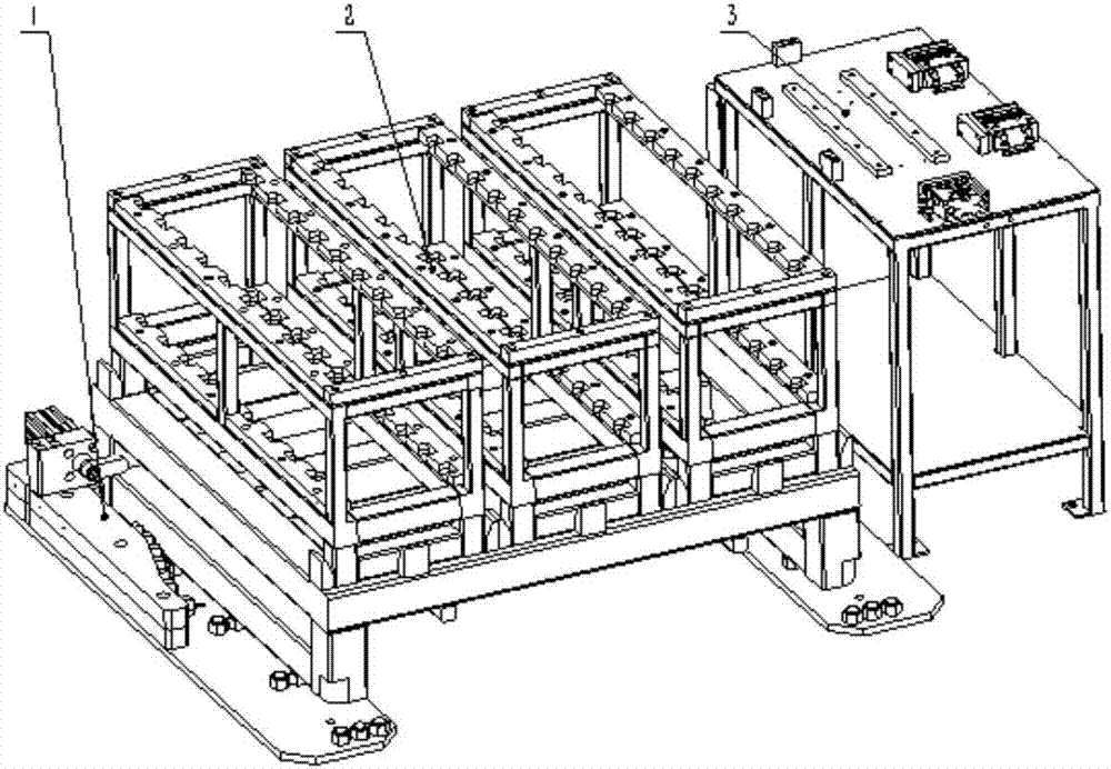
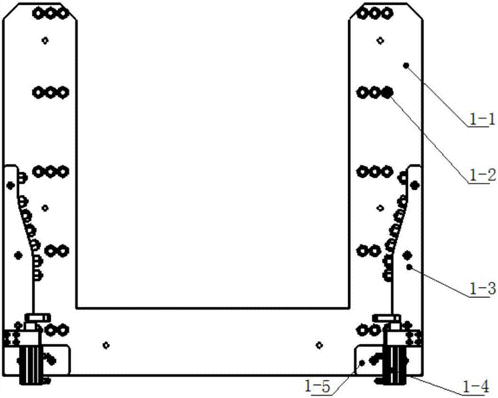
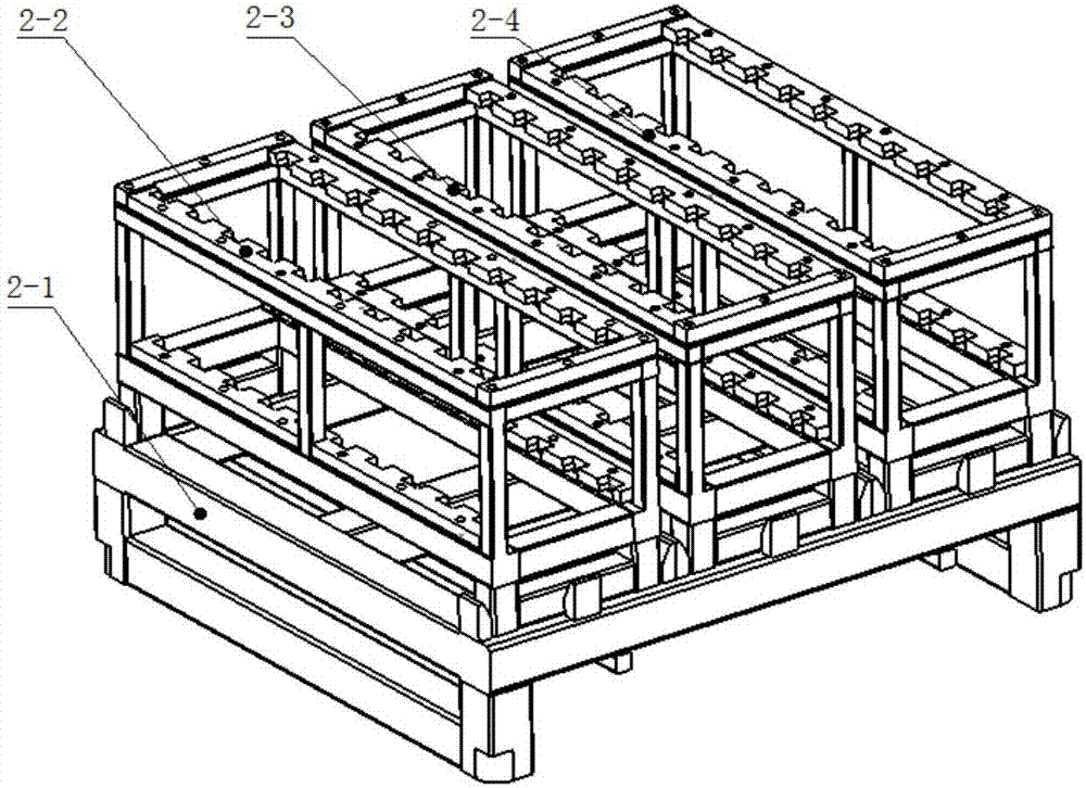
The invention discloses a material rack mechanism achieving automatic guiding and locking. The material rack mechanism comprises a material rack guiding and locking mechanism, a primary-secondary material rack and a preliminary locating material table. A guiding and clamping mechanism is arranged on the material rack guiding and locking mechanism. The primary-secondary material rack is arranged on the inner side of the guiding and clamping mechanism and is guided, clamped and located through the guiding and clamping mechanism. A locating mechanism is arranged on the preliminary locating material table, and the preliminary locating material table is used for cooperating with the material rack guiding and locking mechanism to carry out secondary locating on workpieces on the primary-secondary material rack to complete material replacement. The material rack mechanism has the beneficial effects that the material replacement time is short; the production efficiency is high; locating is reliable; the function of secondary locating is achieved; and the varieties of the replaced workpieces are simple.

Description

technical field [0001] The invention belongs to the technical field of mechanical automation, and in particular relates to a material rack mechanism that is always automatically guided and locked. Background technique [0002] Before the mid-1970s, the development of production could not keep up with the growth of demand, and the market in the world was still a seller's market. Products are in a state of short supply, and enterprises only need to ensure production capacity and basic product quality. Therefore, the biggest feature of the enterprise at that time was to reduce costs by mass production of a single variety (or a few varieties). After the 1970s, with the development of production and economy, the market demand gradually became saturated, the actions of consumers became more selective, and the market demand began to develop in the direction of diversification. Customers have higher and more demanding requirements for product quality and performance. Not only the...

Claims


Application Information

Patent Timeline
IPC IPC(8): B25H3/04
CPCB25H3/04
Inventor 白钊刘进奇刘旭
Owner 西安精雕软件科技有限公司
Why Eureka
Try Eureka