A method of welding modular steel frames using a rotating device

A rotating device and steel frame technology, applied in auxiliary devices, welding equipment, auxiliary welding equipment, etc., can solve the problems of difficult quality control of assembly welding, large hidden dangers of operation safety, high cost and high cost, so as to achieve safe rotation and ensure the quality of assembly welding , The effect of high welding efficiency

Active Publication Date: 2019-05-31
MCC TIANGONG GROUP +1
View PDF6 Cites 0 Cited by
  • Summary
  • Abstract
  • Description
  • Claims
  • Application Information

AI Technical Summary

Problems solved by technology

[0009] The purpose of the present invention is to provide a method of using a rotating device for modular steel frame assembly welding, which solves the problems in the prior art that the assembly and welding efficiency is low and the operation is low due to the need to erect and move scaffolds and platforms, and the need for steel frame hoisting and flipping. Large potential safety hazards, difficult welding quality control, high cost and other issues

Method used


Image

  • A method of welding modular steel frames using a rotating device
  • A method of welding modular steel frames using a rotating device
  • A method of welding modular steel frames using a rotating device

Examples


Embodiment Construction

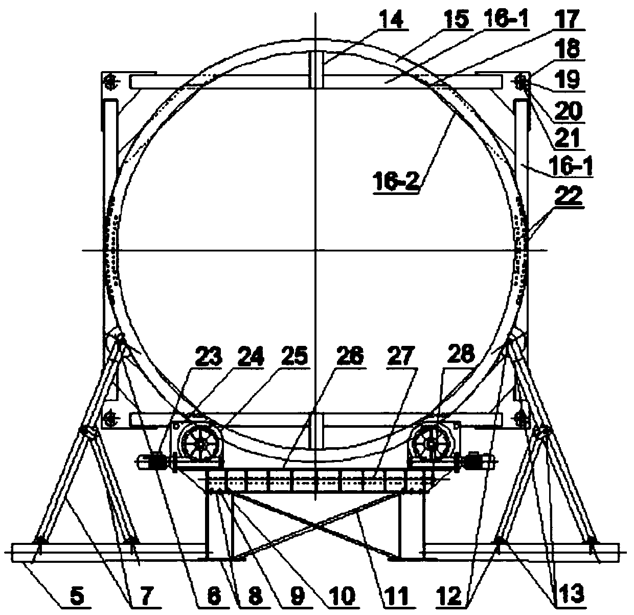
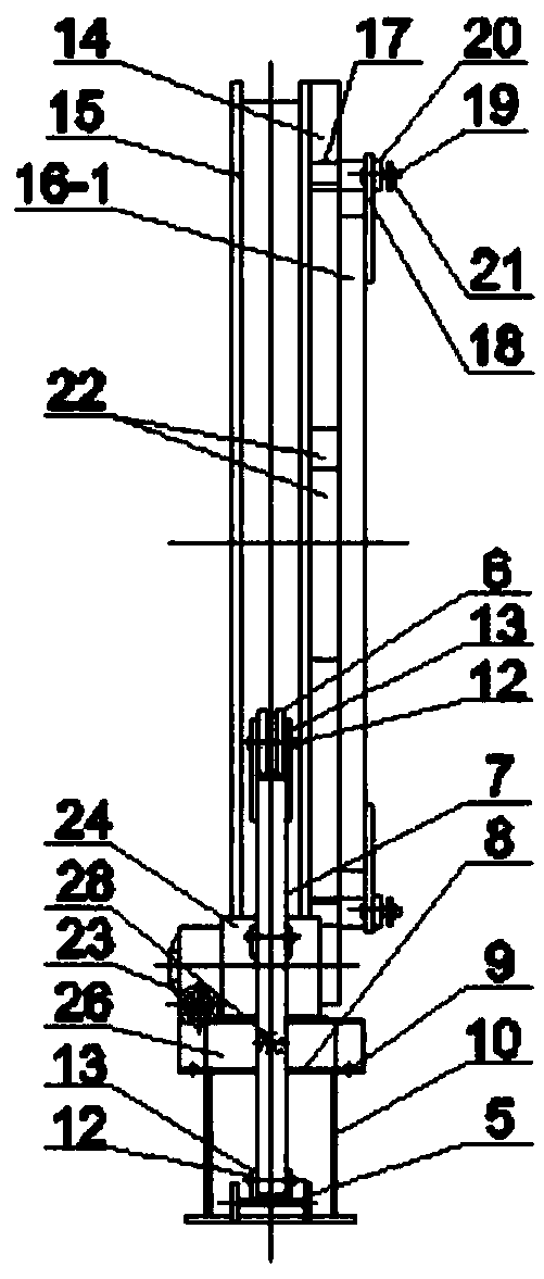
[0046] A method for welding a modular steel frame using a rotating device, comprising the following steps:

[0047] 1. Make the rotating device: such as figure 2 , 3 As shown: the rotating device is composed of a side support frame part, an electric roller frame part and a fixed connection support part.

[0048] ① if Figure 4 , 5 As shown: the lateral support frame part is composed of two sets of support devices, each set of support devices includes a vertically arranged H-shaped steel bracket 10, an I-shaped steel base 5 connected horizontally with the H-shaped steel bracket, and passive rollers 6 and I-shaped steel A rectangular steel pipe support rod 7 is connected between the bases 5, and the support rod is fixedly connected to the I-shaped steel base and the passive roller through the fixed pin 12, and the passive roller 6 is rolled and supported on the circular roller under the action of the rectangular steel pipe support rod 7 The two sides of the track 15 prevent...


PUM


Abstract

The invention provides a method for conducting assembly welding of a modular steel frame through rotary devices. The method for conducting assembly welding of the modular steel frame through the rotary devices comprises the following steps that (1) the two rotary devices are arranged at the two corresponding ends in the length direction of the modular steel frame separately, wherein each rotary device is composed of a lateral supporting frame part, an electric wheel frame part and a fixed connecting support part; (2) the modular steel frame is hoisted and connected to the rotary devices, and the rotary devices are fixedly connected with modular corner pieces at the two ends of the modular steel frame; (3) after connection of the modular steel frame, a driving wheel is driven by a motor and transmission piece to rotate together with a round wheel track and the modular steel frame, and assembly welding is conducted after components needing to be assembly-welded to different positions of the modular steel frame are rotated to a worker operating position; and (4) after all the components are assembly-welded, the modular steel frame obtained after assembly welding is separated from the rotary devices, and thus assembly welding of the modular steel frame is completed. According to the method for conducting assembly welding of the modular steel frame through the rotary devices, the operating process is simple, the assembly welding efficiency is high, various operation risks are lowered, and the assembly welding quality is ensured.

Description

Technical field: [0001] The invention belongs to the technical field of steel structure modular buildings, and relates to a method for assembling and welding modular steel frames by using a rotating device. Background technique: [0002] The steel structure modular building is a highly integrated prefabricated building, usually consisting of a steel structure frame and a matching three-plate system plus decoration. Among them, the steel structure frame is generally a box-type space structure formed by welding square steel, H-shaped steel and other components. It is usually assembled and welded by manual arc welding on the factory assembly line. However, due to the characteristics of its space structure, assembly welding often requires such figure 1 The shown auxiliary scaffolding, horse stool or assembly welding platform, etc., together with component turning, can complete the welding of different parts of the weld (high position uses scaffolding and platforms and other devi...

Claims


Application Information

Patent Timeline
Patent Type & Authority Patents(China)
IPC IPC(8): B23K37/047
CPCB23K37/047
Inventor 李显峰林会明张健高春生王延臣高振旭
Owner MCC TIANGONG GROUP
Why Eureka
Try Eureka