Ore cleaning device used in mining industry
A cleaning device and ore technology, applied in the direction of using liquid cleaning method, drying gas arrangement, cleaning method and utensils, etc., can solve the problems of low work efficiency, slow cleaning speed, complicated operation, etc., and achieve good cleaning effect.
- Summary
- Abstract
- Description
- Claims
- Application Information
AI Technical Summary
Problems solved by technology
Method used
Image


Examples
Embodiment 1
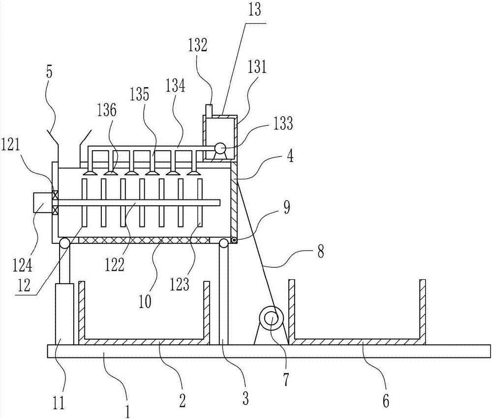
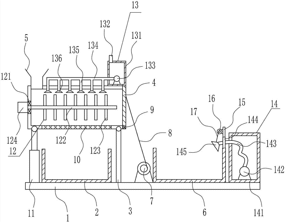
[0027] An ore cleaning device for mining, such as Figure 1-3 As shown, it includes a bottom plate 1, a first collection frame 2, a support rod 3, a baffle 4, a lower hopper 5, a second collection frame 6, a first electric reel 7, a first pull wire 8, a torsion spring 9, a cleaning Box 10, cylinder 11, stirring device 12 and cleaning device 13, the top of the bottom plate 1 is connected by bolts from left to right, and the cylinder 11, the first collecting frame 2, the support rod 3, the first electric reel 7 and In the second collection frame 6, the air cylinder 11 is arranged vertically, and the telescopic rod of the air cylinder 11 is equipped with a cleaning box 10 through a pin connection. The right side of the outer bottom of the cleaning box 10 is connected to the top of the support rod 3 through a pin connection. The bottom of the box 10 is mesh-shaped. The cleaning box 10 is located directly above the first collection frame 2. The cleaning box 10 is equipped with a sti...
Embodiment 2
[0029] An ore cleaning device for mining, such as Figure 1-3 As shown, it includes a bottom plate 1, a first collection frame 2, a support rod 3, a baffle 4, a lower hopper 5, a second collection frame 6, a first electric reel 7, a first pull wire 8, a torsion spring 9, a cleaning Box 10, cylinder 11, stirring device 12 and cleaning device 13, the top of the bottom plate 1 is connected by bolts from left to right, and the cylinder 11, the first collecting frame 2, the support rod 3, the first electric reel 7 and In the second collection frame 6, the air cylinder 11 is arranged vertically, and the telescopic rod of the air cylinder 11 is equipped with a cleaning box 10 through a pin connection. The right side of the outer bottom of the cleaning box 10 is connected to the top of the support rod 3 through a pin connection. The bottom of the box 10 is mesh-shaped. The cleaning box 10 is located directly above the first collection frame 2. The cleaning box 10 is equipped with a sti...
Embodiment 3
[0032] An ore cleaning device for mining, such as Figure 1-3 As shown, it includes a bottom plate 1, a first collection frame 2, a support rod 3, a baffle 4, a lower hopper 5, a second collection frame 6, a first electric reel 7, a first pull wire 8, a torsion spring 9, a cleaning Box 10, cylinder 11, stirring device 12 and cleaning device 13, the top of the bottom plate 1 is connected by bolts from left to right, and the cylinder 11, the first collecting frame 2, the support rod 3, the first electric reel 7 and In the second collection frame 6, the air cylinder 11 is arranged vertically, and the telescopic rod of the air cylinder 11 is equipped with a cleaning box 10 through a pin connection. The right side of the outer bottom of the cleaning box 10 is connected to the top of the support rod 3 through a pin connection. The bottom of the box 10 is mesh-shaped. The cleaning box 10 is located directly above the first collection frame 2. The cleaning box 10 is equipped with a sti...
PUM
 Abstract
Description
Claims
Application Information
 - Generate Ideas
- Intellectual Property
- Life Sciences
- Materials
- Tech Scout
- Unparalleled Data Quality
- Higher Quality Content
- 60% Fewer Hallucinations
Browse by: Latest US Patents, China's latest patents, Technical Efficacy Thesaurus, Application Domain, Technology Topic, Popular Technical Reports.
© 2025 PatSnap. All rights reserved.Legal|Privacy policy|Modern Slavery Act Transparency Statement|Sitemap|About US| Contact US: help@patsnap.com