Improved energy-saving stove

An energy-saving stove and stove body technology, applied in the field of stoves, can solve the problems of increasing the power of the motor, being easy to meet, affecting food, etc., and achieving the effects of improving the heat difference, changing the heating efficiency, and improving the heating efficiency.

Inactive Publication Date: 2017-09-12
施美琴
View PDF7 Cites 0 Cited by
  • Summary
  • Abstract
  • Description
  • Claims
  • Application Information

AI Technical Summary

Problems solved by technology

[0003] At present, the traditional range hoods used in the market and at home have many disadvantages. For example, if the hoisting is high, the efficiency of the range hood will be reduced. The efficiency of dealing with lampblack is at most 70%, and 30% is polluting the indoor environment, so traditional range hoods are not the best kitchen environmental protection equipment
[0004] Now there are downdraft range hoods on the market, which can absorb more than 90% of the oil fume, but there are the following problems: 1. The two airflows under the pot and in the pot must be completely sucked away so that the oil fume can be released. This will inevitably increase the power of the motor; the residence time of the flame at the bottom of the pot itself is short, and it will be even shorter when the high-power motor is pumped, so the supply of gas must be increased, which is to use one kind of energy to consume another. One kind of energy is quite unfavorable to energy saving; two, after a long time of use, the inside of the oil suction hole and the side of the pot are dirty. When the range hood is turned off, the fume in the fume treatment part will flow back, and It will affect food, and over time, it will make people feel that the food hygiene situation has seriously deteriorated; 3. After a long time of use, the effect of dealing with oil fume will be reduced, and consumers have no ability to disassemble, wash and maintain, and cannot remove stains

Method used


Image

  • Improved energy-saving stove
  • Improved energy-saving stove
  • Improved energy-saving stove

Examples


Embodiment Construction

[0025] Below in conjunction with accompanying drawing and embodiment the present invention is described in further detail:

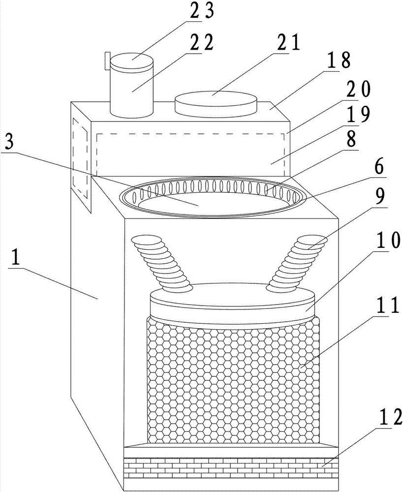
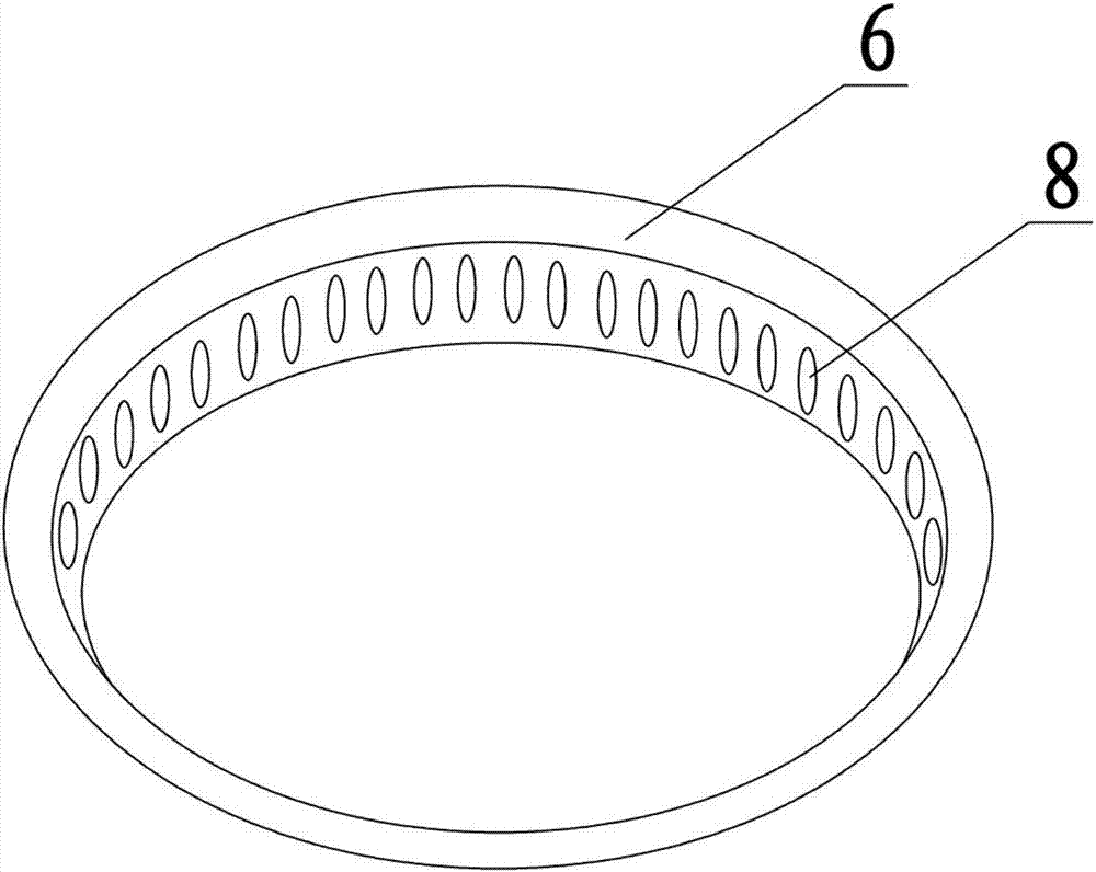
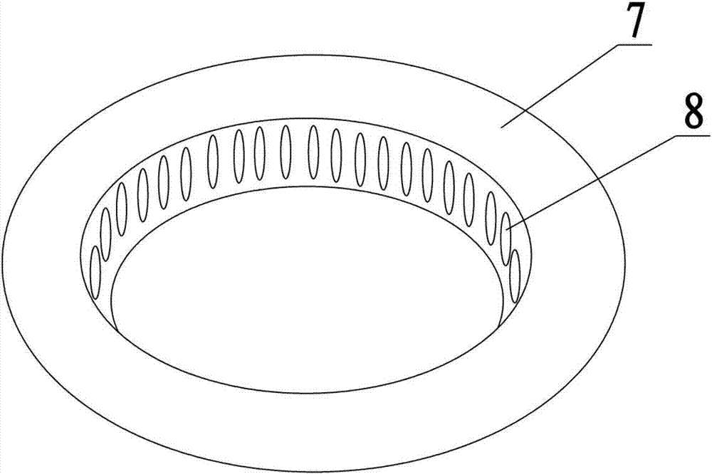
[0026] As an embodiment of an improved energy-saving cooker described in the present invention, such as figure 1 , figure 2 , image 3 , Figure 4 , Figure 5 , Image 6 and Figure 7 As shown, it includes a casing 1, a stove body 2, a pot 3, a water tank 4, a return mechanism, a range fume mechanism, an air diffuser mechanism and an ignition mechanism. The casing 1 is arranged outside the stove body 2, and the water tank 4 The rear of the casing 1 is provided, the lower part of the stove body 2 is provided with a vent 5, the ignition mechanism is arranged at the vent 5, the pot 3 is erected on the stove body 2, and the return mechanism surrounds The pot 3 is arranged around, the air diffuser is arranged around the return mechanism, and communicates with the stove body 2, and the oil suction mechanism is arranged inside the housing 1 and is locate...


PUM


Abstract

The invention relates to the technical field of stoves, in particular to an improved energy-saving stove. The improved energy-saving stove comprises a shell, a stove body, a pot, a water tank, an ignition mechanism, a gas dispersing mechanism, a cooking fume suction mechanism and a flow return mechanism. The ignition mechanism comprises a fire ejection lotus seedpod and a wind control panel. The fire ejection lotus seedpod is arranged at a ventilation opening. The wind control panel is arranged below the fire ejection lotus seedpod and is inserted into the stove body. A stove core is arranged between the ignition mechanism and the pot. The stove core comprises a core part and an enclosure. The core part is in a hollow cylinder shape with the two ends being opened. The enclosure is in a hollow inverted circular truncated cone shape with the two ends being opened. The core part and the enclosure are coaxially arranged on the upper surface of the fire ejection lotus seedpod, and a spiral groove rotating in a clockwise mode is formed in the outer side face of the core part. Long-bar-shaped grooves distributed in a divergence mode are formed in the inner side face of the enclosure. A plurality of heat exchange holes are formed in the radial direction of the core part.

Description

[0001] This application was filed on September 18, 2015, the application number is 201510607133.X, and the title of the invention is a divisional application of a patent for an energy-saving stove. technical field [0002] The invention relates to the technical field of stoves, in particular to an improved energy-saving stove. Background technique [0003] At present, the traditional range hoods used in the market and at home have many disadvantages. For example, if the hoisting is high, the efficiency of the range hood will be reduced. The efficiency of dealing with lampblack is at most 70%, and 30% is polluting the indoor environment, so traditional range hoods are not the best kitchen environmental protection equipment. [0004] Now there are downdraft range hoods on the market, which can absorb more than 90% of the oil fume, but there are the following problems: 1. The two airflows under the pot and in the pot must be completely sucked away so that the oil fume can be re...

Claims


Application Information

Patent Timeline
Patent Type & Authority Applications(China)
IPC IPC(8): F24C13/00F24C15/20
CPCF24C13/00F24C15/2035F24C15/2071
Inventor 施美琴
Owner 施美琴
Why Eureka
Try Eureka