


Quick Research
Generate reliable direction feasibility study reports for your R&D in just a few steps.

Technical Q&A
Discover and master advanced knowledge NOW. Basics, ideas, possibilities, all at once.

Find Solutions
As an expert in R&D theories, this can generate solutions to your technical problems instantly.

Evaluate Feasibility
Analyze your overall solution with one click, know your potential R&D risks in advance.

Monitor Landscape
Get weekly tech updates, stay abreast of the latest tech innovations and key insights.
Electronic candle lamp structure
A technology of electronic candles and LED lamps, applied in the field of lamps and lanterns, can solve the problems of unrealistic effect, insufficient simulation degree, limited viewing angle, etc.
- Summary
- Abstract
- Description
- Claims
- Application Information
AI Technical Summary
Problems solved by technology
Method used
Image

Examples
Embodiment 1
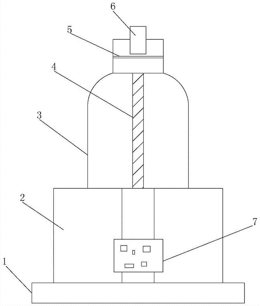
[0020] Embodiment one, as attached figure 1 As shown, the smoke generating device includes a container 3, an ultrasonic oscillating circuit 7, a liquid guide core 4 and an ultrasonic atomizing sheet 5, the container 3 is filled with atomized liquid, the ultrasonic oscillating circuit 7 is connected to the base 2 and Connect with the power module through the line, the lower end of the liquid guide core 4 extends into the bottom of the container 3 and the upper end is connected with the ultrasonic atomizing sheet 5, the ultrasonic atomizing sheet 5 is connected with the ultrasonic oscillation circuit 7 through the line, and the ultrasonic atomizing sheet is equipped with Smoke through the hole. The liquid guide is preferably a cotton wick. The power module provides power for the ultrasonic oscillating circuit. The cotton core uses the principle of siphon to absorb the fluid in the container to the upper end of the cotton core. When the liquid passes through the ultrasonic atomi...
Embodiment 2
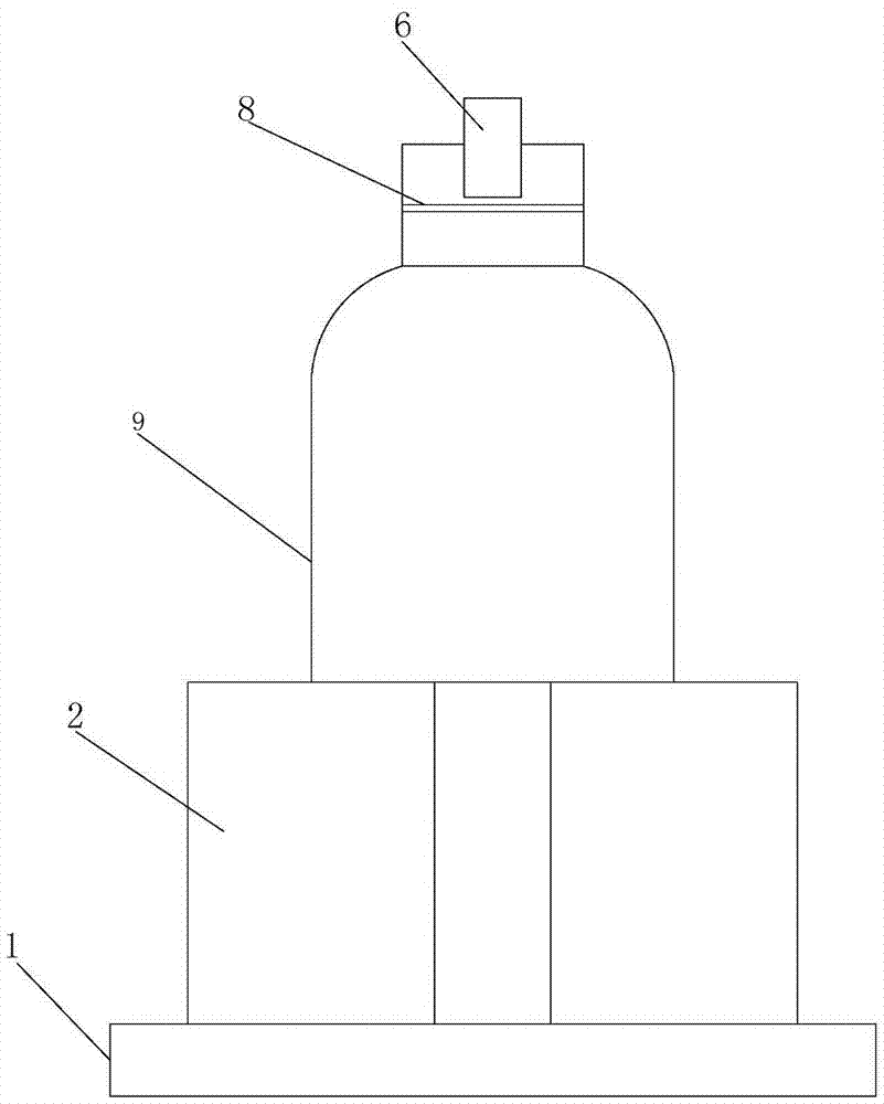
[0021] Embodiment two, as attached figure 2 As shown, the difference from Embodiment 1 is that no ultrasonic oscillation circuit, ultrasonic atomizing sheet and liquid guide core are required. The smoke generating device includes a container 9, a volatile liquid or solid filled in the container 9, and a smoke forming sheet 8 installed in the outlet area of the container, and the smoke forming sheet 8 is provided with a smoke forming hole. The solid can be dry ice or something similar to dry ice, which can be volatilized to form a mist. The aerosol forming sheet is generally arranged in the outlet area of the container.
[0022] In addition, the smoke passing holes on the ultrasonic atomizing sheet and the smoke forming holes on the smoke forming sheet include but are not limited to circular, square, sheet or irregular shapes. By setting different shapes, different smoke shapes can be formed, which can be flexibly selected and set according to the place of use.
[0023...
PUM
 Abstract
Description
Claims
Application Information
 - R&D Engineer
- R&D Manager
- IP Professional
- Industry Leading Data Capabilities
- Powerful AI technology
- Patent DNA Extraction
Browse by: Latest US Patents, China's latest patents, Technical Efficacy Thesaurus, Application Domain, Technology Topic, Popular Technical Reports.
© 2024 PatSnap. All rights reserved.Legal|Privacy policy|Modern Slavery Act Transparency Statement|Sitemap|About US| Contact US: help@patsnap.com