
Fuel pump module

A fuel pump module and fuel pump technology, applied to liquid fuel feeders, engine components, machines/engines, etc., can solve the problems of rising manufacturing costs, time and labor, and achieve simplified structure, reduced manufacturing processes, and reduced The effect of manufacturing costs

Active Publication Date: 2017-09-12
HITACHI ASTEMO LTD
View PDF6 Cites 1 Cited by
  • Summary
  • Abstract
  • Description
  • Claims
  • Application Information

AI Technical Summary

Problems solved by technology

Time and labor are required for molding and assembly operations such as forming grooves, inserting sealing parts, and aligning flat surfaces, resulting in an increase in manufacturing costs

Method used


Image

  • Fuel pump module
  • Fuel pump module

Examples


Embodiment Construction

[0025] Hereinafter, one embodiment of the present invention will be described with reference to the drawings.

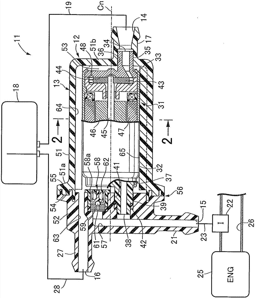
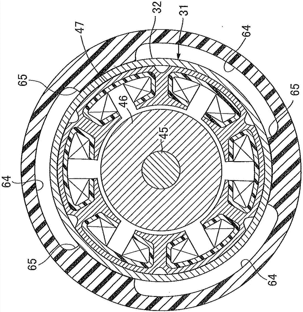
[0026] figure 1 The overall configuration of the vehicle fuel supply system 11 is schematically shown. The fuel supply system 11 has a fuel pump module 12 according to one embodiment of the present invention. The pump housing 13 of the fuel pump module 12 is formed in a cylindrical shape with a central axis Cn. An inlet 14 is defined at one end in the axial direction of the cylinder. An outlet 15 and a return port 16 are divided at the other end in the axial direction of the cylinder. The inlet 14 is formed by a pipe connection 17 . A fuel pipe 19 connected to a fuel tank 18 is combined with a pipe joint 17 . The outlet 15 is likewise formed by a pipe connection 21 . For example, a fuel pipe 23 connected to a fuel injection device 22 is coupled to the pipe joint 21 . The fuel injection device 22 faces an intake passage 26 connected to an intake passage of, for...


PUM


Abstract

The invention provides a fuel pump module, which has the advantages that good sealing is established and the manufacturing steps and the manufacturing cost are reduced. The fuel pump module (12) comprises a fuel pump (31), which comprises a suction inlet in a first end and a discharge outlet (38) in a second end opposite to the first end; a first shell part (51), which is made of resin and holds the first end and the second end of the fuel pump (31); and a second shell part (52), which has a continuous welding area (56) in the whole circumference of an open end (55) butt-jointed to the open end (54) of the first shell part (51). A storage space (53) of the fuel pump (31) is formed between the first shell part (51) and the second shell part (52).

Description

technical field [0001] The present invention relates to a so-called in-line fuel pump module arranged outside a fuel tank. Background technique [0002] Patent Document 1 discloses a fuel supply device for a two-wheeled vehicle. The fuel supply device has a pump body and a pump cover. The pump body and the pump cover are combined to define a storage space for the fuel pump. [0003] Existing patent documents [0004] Patent Document 1: Japanese Patent Laid-Open No. 2006-142842 [0005] The pump cover overlaps the open end of the pump body in a facing manner. A groove surrounding the storage space is formed on the joint surface of the pump body, and a seal member is fitted into the groove. The tightness is established here by the joint surfaces. Forming and assembling operations such as formation of grooves, insertion of sealing members, and alignment between flat surfaces take time and labor, leading to an increase in manufacturing costs. Contents of the invention ...

Claims


Application Information

Patent Timeline
Patent Type & Authority Applications(China)
IPC IPC(8): F02M37/04F02M37/10
CPCF02M37/04F02M37/103
Inventor 田中聪
Owner HITACHI ASTEMO LTD
Learn More