PCB welding jig

A technology for welding jigs and PCB boards, which is applied in the direction of PCB positioning during processing and assembling printed circuits with electrical components, which can solve problems such as troubles and achieve the effect of convenient use, compact structure and convenient use.

Active Publication Date: 2017-09-08
佛山市顺德区金御海电子科技有限公司
View PDF7 Cites 2 Cited by
  • Summary
  • Abstract
  • Description
  • Claims
  • Application Information

AI Technical Summary

Problems solved by technology

The printed circuit board we usually refer to refers to the bare board - that is, the circuit board without components. The traditional PCB board welding fixture is a welding fixture designed and manufactured according to the outer dimensions of the welding product at the time of design. The structure is fixed and also It means that one kind of jig can only be used for the welding of one product. With the continuous update of the manufacturer's products, new jigs must be manufactured, causing unnecessary trouble

Method used


Image

  • PCB welding jig

Examples


Embodiment

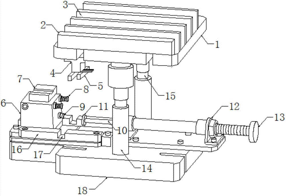
[0013] Example: such as figure 1 As shown, a PCB board welding jig of the present invention includes a support cover 1 and a base 18, a telescopic rod 15 is fixedly connected to the bottom of the support cover 1, a sleeve 14 is fixed on the base 18, and the telescopic rod 15 is embedded in Inside the sleeve 14 and movably connected with it, the bottom of the support cover 1 is connected with a clamping head 5 through a connector 4, a positioning block 6 is fixed on one end of the surface of the base 18, and an elastic support 8 is fixed on the side end of the positioning block 6, and the positioning block 6 An air pump 7 is installed on the top, and an air nozzle 9 is installed on the positioning block 6 on the bottom side of the elastic support 8, and the air nozzle 9 communicates with the air pump 7, and a positioning piece 12 is fixed on one end of the base 18, and the positioning piece 12 passes through a threaded Rod 13, one end of threaded rod 13 is connected with positi...


PUM


Abstract

The invention discloses a PCB welding jig. The PCB welding jig comprises a supporting cover plate and a base, wherein the bottom of the supporting cover plate is fixedly connected with a telescopic rod; a sleeve is fixed on the base; the telescopic rod is embedded in the sleeve and is movably connected with the sleeve; the bottom of the supporting cover plate is connected with a clamping head through a connecting piece; a positioning block is fixed at one end of the surface of the base; an elastic supporting piece is fixed on the side end face of the positioning block; an air pump is installed on the positioning block; an air nozzle is installed on the positioning block on the bottom of the elastic supporting block, and communicates with the air pump; a positioning piece is fixed at one end of the base, and a threaded rod is arranged on the positioning piece in a penetrated manner; one end of the threaded rod is connected with a positioning rod, and an extrusion head is fixed at the end of the positioning rod. The PCB welding jig is compact in structure and convenient to use, a PCB can be clamped well, the PCB is extremely stable in the welding process through multi-dimensional positioning, and a PCB to be machined is convenient to place in the welding process, so that the PCB welding jig is convenient for workers to use, and the machining time is reduced.

Description

technical field [0001] The invention relates to a PCB board welding jig, which belongs to the technical field of PCB board processing equipment. Background technique [0002] PCB circuit board, also known as printed circuit board, is the provider of electrical connection for electronic components. Its development has a history of more than 100 years; its design is mainly layout design; the main advantage of using circuit boards is to greatly reduce wiring and assembly errors, improve the level of automation and production labor rate, because printed circuit boards are not general terminals Therefore, the definition of the name is slightly confusing. For example, the motherboard used for personal computers is called the motherboard, and cannot be directly called the circuit board. Although there are circuit boards in the motherboard, they are not the same. Therefore, the assessment industry The two are related but cannot be said to be the same. Another example: because ther...

Claims


Application Information

Patent Timeline
IPC IPC(8): H05K3/34
CPCH05K3/34H05K2203/15
Inventor 周轲
Owner 佛山市顺德区金御海电子科技有限公司
Why Eureka
Try Eureka