Appearance detection device of fingerprint module based on CCD image sensor

An image sensor and fingerprint module technology, applied in the detection field, can solve problems such as health hazards of inspectors, slow detection speed, and cost reduction, and achieve the effects of avoiding detection blind spots, saving manpower, and reducing costs

Active Publication Date: 2019-05-31
KUNSHAN KERSEN SCI & TECH
View PDF1 Cites 0 Cited by
  • Summary
  • Abstract
  • Description
  • Claims
  • Application Information

AI Technical Summary

Problems solved by technology

[0003] The object of the present invention is to provide a fingerprint module appearance detection device based on a CCD image sensor. The fingerprint module appearance detection device can quickly detect by taking photos at a high speed, and solve the problems of slow detection and missed detection in the current human eye detection. High detection rate and easy to cause harm to the health of testing personnel, high detection efficiency, stable detection results and no detection errors, saving manpower and greatly reducing costs

Method used


Image

  • Appearance detection device of fingerprint module based on CCD image sensor
  • Appearance detection device of fingerprint module based on CCD image sensor
  • Appearance detection device of fingerprint module based on CCD image sensor

Examples


Embodiment 1

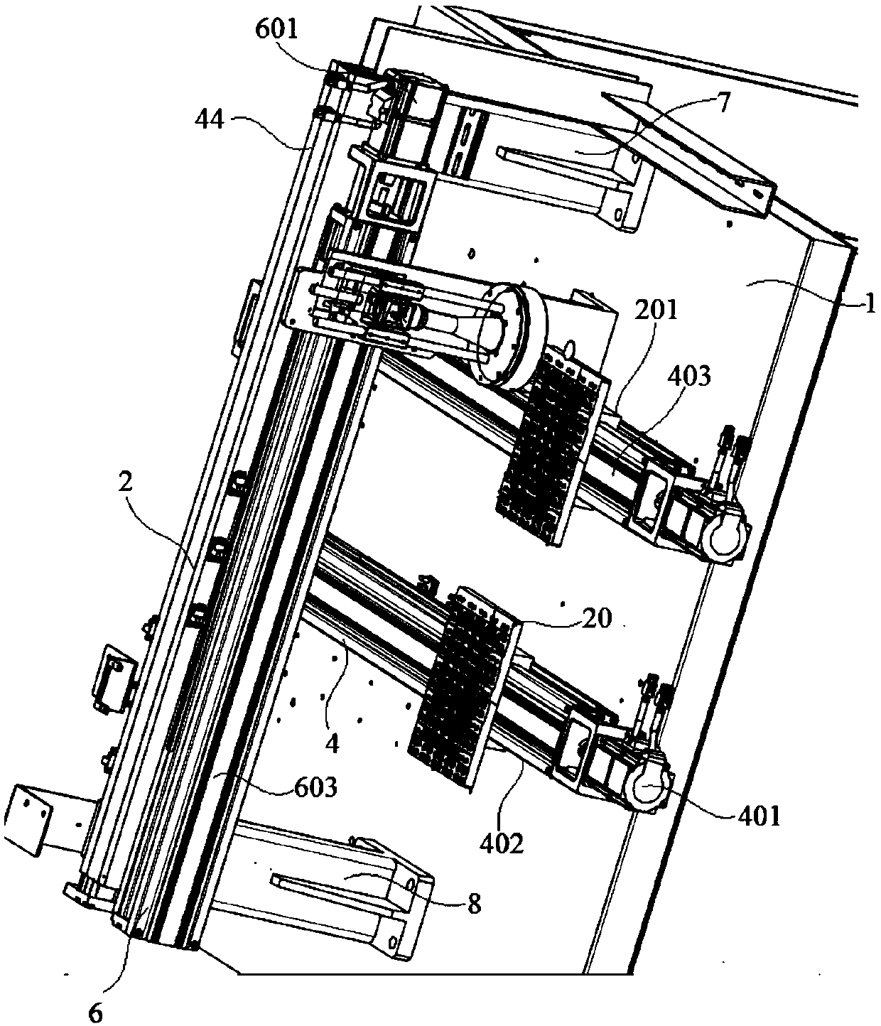
[0023] Embodiment 1: A fingerprint module appearance detection device based on a CCD image sensor, including a base 1, a support frame 2 installed on the base 1, an X-direction transmission device 4 and a Y-direction transmission device 6, and the support frame 2 is composed of The left column 7, the right column 8 and a crossbeam are formed, and the left column 7 and the right column 8 are respectively fixed on both sides of the upper surface of the base 1. Installed on the upper surface of the base 1 and the front and rear sides of the beam of the support frame 2 respectively;

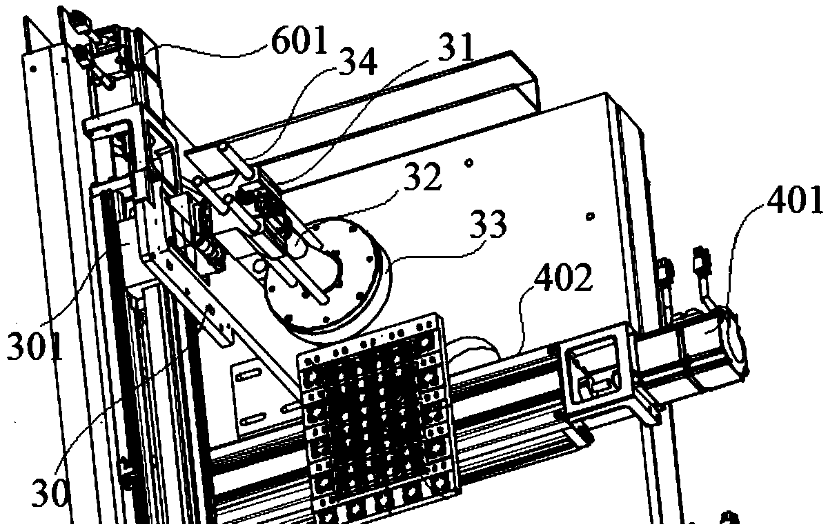
[0024] The X-direction conveying device 4 further includes an X-direction motor 401, two X-direction rails 402, an X-direction screw 403 and an X-direction nut. The X-direction motor 401 is installed on the end of the base 1 opposite to the feed inlet, so The X-direction screw 403 is installed on the base 1 and connected to the X-direction motor 401, the two X-direction rails 402 are respectively loc...

Embodiment 2

[0029] Embodiment 2: A fingerprint module appearance detection device based on a CCD image sensor, including a base 1, a support frame 2 installed on the base 1, an X-direction transmission device 4 and a Y-direction transmission device 6, and the support frame 2 is composed of The left column 7, the right column 8 and a crossbeam are formed, and the left column 7 and the right column 8 are respectively fixed on both sides of the upper surface of the base 1. Installed on the upper surface of the base 1 and the front and rear sides of the beam of the support frame 2 respectively;

[0030] The X-direction conveying device 4 further includes an X-direction motor 401, two X-direction rails 402, an X-direction screw 403 and an X-direction nut. The X-direction motor 401 is installed on the end of the base 1 opposite to the feed inlet, so The X-direction screw 403 is installed on the base 1 and connected to the X-direction motor 401, the two X-direction rails 402 are respectively loc...


PUM


Abstract

A visual inspection device for a fingerprint detection module, comprising: a base (1), as well as a support frame (2) and a transfer device (3) which are mounted on the base (1); the transfer device (3) comprises a first direction transfer device (4) and a second direction transfer device (6); the support frame (2) comprises a first column (7), a second column (8) and a crossbeam (9), the first column (7) and the second column (8) being fixed on two opposite sides of a first surface of the base (1), respectively; a first direction motor (401) is mounted on an end of the base (1) facing away from a feed inlet; a loading board (20), a bottom surface thereof being provided with a sliding block (201), is fixedly connected to a first direction nut (404), the sliding block (201) being inserted into two first direction guiding rails (402), respectively; a first connection part (11) and a second connection part (12) comprise an annular seat (14) and a connection half-ring (15) that is fixed to an end end surface of the annular seat (14); a movable board (30), a rear surface thereof being provided with a sliding block (301), is fixedly connected to a second direction nut (404), the sliding block (301) at a rear side surface of the movable board (30) being embedded within two second direction guiding rails (602), respectively; a camera support frame (31) is provided thereon with a plurality of guiding column through-holes (35), through which guiding columns (34) pass, a plurality of guiding columns (34) passing through the guiding column through-holes (35) respectively and being fixedly connected to an upper surface of a light source (33).

Description

technical field [0001] The invention relates to a fingerprint module appearance detection device based on a CCD image sensor, and relates to the technical field of detection. Background technique [0002] In the prior art, the detection of the chamfer of the fingerprint ring is mostly through manual measurement, and the detection method is to use strong light to irradiate the parts to be detected, and then detect and distinguish through human eyes. The inspection rate is high, and the strong light is easy to affect the eyesight of the inspectors. In addition, it is also possible to calculate the chamfer of the fingerprint ring after taking pictures with the camera, but in the process of taking pictures, the edge of the fingerprint ring is difficult to determine, so there are certain errors in the calculated chamfer of the fingerprint ring. In view of the above problems, in order to meet the needs of industrial production, it is necessary to develop a fully automatic testing...

Claims


Application Information

Patent Timeline
Patent Type & Authority Patents(China)
IPC IPC(8): G01B11/26
CPCG01B11/26
Inventor 徐金根朱磊蔡成林何忠伟
Owner KUNSHAN KERSEN SCI & TECH
Why Eureka
Try Eureka