
Yarn feeding nozzle

A yarn feeder and yarn feeding technology, applied in the field of yarn feeders, can solve the problems of insufficient air layer in the middle and needle marks on the front of the fabric, and achieve the effects of reasonable structure, quick adjustment and convenient use.

Active Publication Date: 2017-09-08
GUANGDONG ESQUEL TEXTILES CO LTD
View PDF6 Cites 0 Cited by
  • Summary
  • Abstract
  • Description
  • Claims
  • Application Information

AI Technical Summary

Problems solved by technology

In the circular knitting machine, the double-sided machines on the market cannot knit, mainly because the fabric is made of cotton yarn on both sides, and nylon yarn in the middle. The following problems mainly occur when the surface machine is knitting: 1. The air layer in the middle is not strong enough; 2. There are needle marks on the front of the fabric;

Method used


Image

  • Yarn feeding nozzle

Examples


Embodiment Construction

[0018] In order to facilitate the understanding of the present invention, the present invention will be described more fully below with reference to the associated drawings. Preferred embodiments of the invention are shown in the accompanying drawings. However, the present invention can be embodied in many different forms and is not limited to the embodiments described herein. On the contrary, these embodiments are provided to make the understanding of the disclosure of the present invention more thorough and comprehensive.

[0019] It should be noted that when an element is referred to as being “fixed” to another element, it can be directly on the other element or there can also be an intervening element. When an element is referred to as being "connected to" another element, it can be directly connected to the other element or intervening elements may also be present.

[0020] Unless otherwise defined, all technical and scientific terms used herein have the same meaning as...


PUM


Abstract

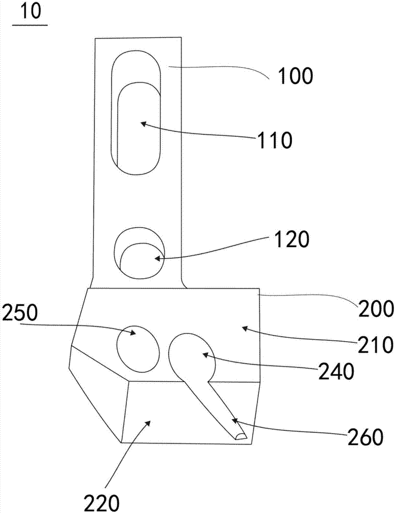
The invention discloses a yarn feeding nozzle which comprises a fixing seat and a yarn feeding seat. The bottom of the fixing seat is connected with the top of the yarn feeding seat, a fixing hole is formed in the fixing seat, and the fixing seat can be mounted and connected with a cabinet of a weaving machine via the fixing hole. A side surface of the yarn feeding seat is outwardly protruded to form an upward first oblique plane and a downward second oblique plane; a first yarn feeding hole, a second yarn feeding hole and a yarn feeding straight slot are formed in the yarn feeding seat in a perforated manner, an opening in one end of the first yarn feeding hole and an opening in one end of the second yarn feeding hole are formed in the bottom surface of the yarn feeding seat, an opening in the other end of the first yarn feeding hole and an opening in the other end of the second yarn feeding hole are formed in the first oblique plane, an opening in a notch in one end of the yarn feeding straight slot is formed in the bottom surface of the yarn feeding seat, an opening in a notch in the other end of the yarn feeding straight slot is formed in the second oblique plane, and the opening, which is formed in the second oblique plane, of the yarn feeding straight slot is communicated with the opening, which is formed in the first oblique plane, of the second yarn feeding hole. The yarn feeding nozzle has the advantages that the problem of counter looping can be solved, and the yarn feeding nozzle is convenient to use and wide in application range.

Description

technical field [0001] The invention relates to the field of textile machinery, in particular to a yarn feeding nozzle. Background technique [0002] Knitted rack health fabric has the characteristics of soft texture, moisture absorption and breathability, perspiration and warmth, strong air permeability, soft and smooth hand feeling, good skin feeling, strong three-dimensional effect, etc., and has excellent elasticity and extensibility. It is the main fabric for sports, casual wear and professional wear. In the circular knitting machine, the double-sided machines on the market cannot knit, mainly because the fabric is made of cotton yarn on both sides, and nylon yarn in the middle. The following problems mainly occur when the surface machine is knitting: 1. The air layer in the middle is not strong enough; 2. There are needle marks on the front of the fabric; Contents of the invention [0003] Based on this, it is necessary to provide a yarn feeding nozzle that is not ...

Claims


Application Information

Patent Timeline
Patent Type & Authority Applications(China)
IPC IPC(8): D04B15/48
CPCD04B15/48
Inventor 黄庆国王剑张华宋彦
Owner GUANGDONG ESQUEL TEXTILES CO LTD
Learn More