
A ground wire bending platform

A grounding wire and platform technology, applied in the field of bending devices, can solve problems affecting construction efficiency, engineering quality, etc., and achieve the effects of avoiding production efficiency reduction, reducing acquisition cost, and improving molding quality.

Active Publication Date: 2018-07-20
CHINA MCC5 GROUP CORP
View PDF4 Cites 0 Cited by
  • Summary
  • Abstract
  • Description
  • Claims
  • Application Information

AI Technical Summary

Problems solved by technology

[0006] Aiming at the above-mentioned problems that affect the construction efficiency and engineering quality caused by the elbows used are non-standard parts during the construction of equipotential bonding for plane lightning protection and grounding, the present invention A grounding wire bending platform is provided. The bending device has a simple structure and is convenient for bending flat rods at the construction site. It can bend bends of specific sizes according to construction needs, so as to reduce the cost of obtaining bends and avoid The purpose of secondary processing; at the same time, when the flat rod is bent, it can well limit the bending deformation direction of the flat rod, which is beneficial to the molding quality of the product

Method used


Image

  • A ground wire bending platform
  • A ground wire bending platform

Examples


Embodiment 1

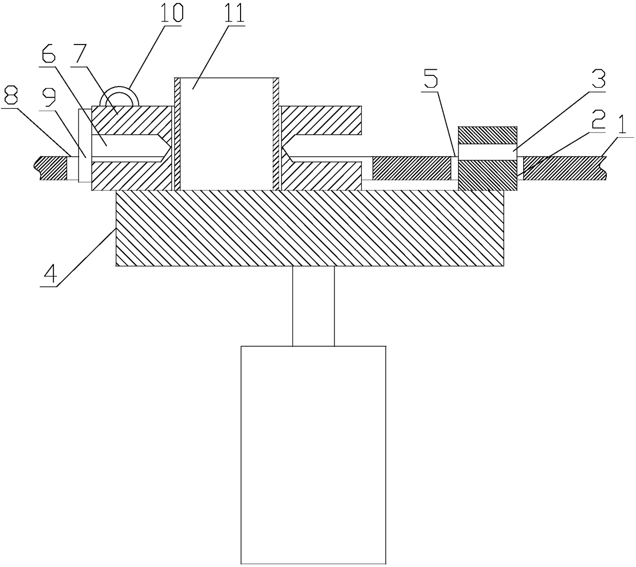
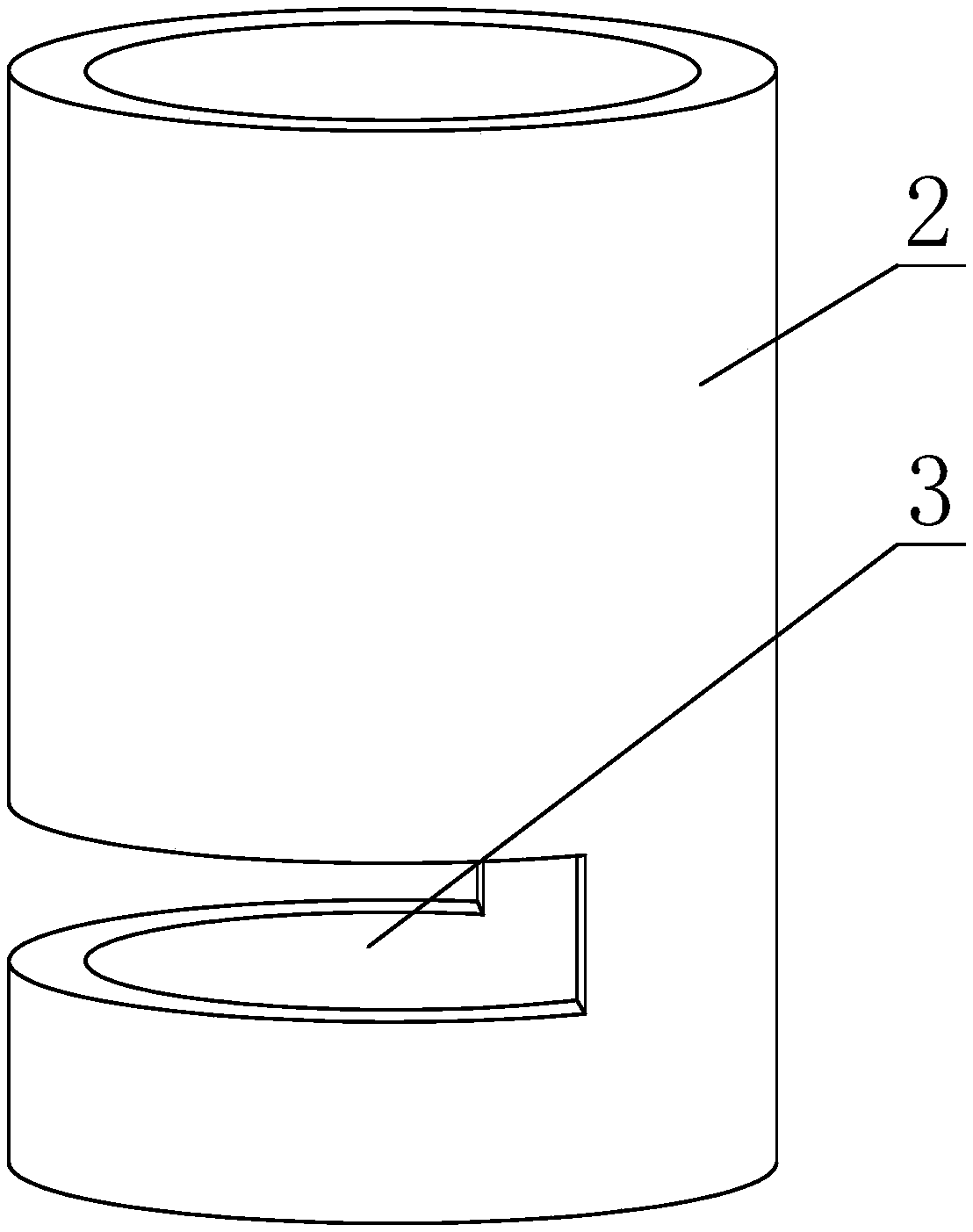
[0027] Such as figure 1 and figure 2 As shown, a grounding wire bending platform includes a platform plate 1, a first gear lever 2, a rotating disk 7 and a rotating shaft 11. The rotating disk 7 can rotate on the axis of the rotating shaft 11 as the rotating shaft 11, and the rotating disk 7 is also provided with An annular ring groove 6, the axis of the ring groove 6 is in line with the axis of the rotating shaft 11, and the turntable 7 and the first gear rod 2 protrude from the second through hole 8 and the first through hole 5 to the platform plate respectively 1, the notch 3 and the ring groove 6 can be fully or partially exposed on the upper side of the platform plate 1;

[0028] A second gear rod 9 is also fixed on the turntable 7, and there is a gap for the flat rod to pass between the second gear rod 9 and the groove bottom of the ring groove 6;

[0029] A notch 3 is also provided on the side of the first gear lever 2;

[0030] The platform plate 1 is also provided...

Embodiment 2

[0035] Such as figure 1 and figure 2 As shown, this embodiment is further limited on the basis of the technical solution provided in Example 1. As a realization solution that is easy to obtain materials on the construction site, the turntable 7 is welded by two neck butt welding flanges, The second gear rod 9 is a rod member welded on the side of the butt welding flange with neck.

[0036] As a specific easy-to-implement connection form, the rotating shaft 11 and the first shift rod 2 are both fixed on the lifting platform 4 , and the rotating disk 7 is provided with a middle hole, and the middle hole is in clearance fit with the rotating shaft 11 .

Embodiment 3

[0038] Such as figure 1 and figure 2 As shown, this embodiment is further limited on the basis of Embodiment 1: for the convenience of confirming the bending degree of the bending part of the flat rod, the surface of the platform plate 1 is also provided with an angle scale for marking the bending angle of the flat rod .

[0039] In order to reduce the weight of this platform, it is easy to carry, and the work does not depend on other power equipment, it also includes a driving device for driving the lifting table 4 to do lifting movement, the driving device includes a threaded rod and an internal threaded cylinder, and the threaded rod and The internally threaded cylinder is threadedly connected, and the lifting table 4 is fixedly connected with the threaded rod or the internally threaded cylinder. In this solution, by applying an external force to force the threaded rod and the internal threaded cylinder to rotate relative to each other, the components composed of the two...


PUM


Abstract

The invention discloses a ground lead bending platform which comprises a platform plate, a first stopping rod, a rotary disc and a rotating shaft. A ring groove is further formed in the rotary disc; a second stopping rod is further fixed to the rotary disc, and a gap allowing a flat rod to penetrate is formed between the second stopping rod and the groove bottom of the ring groove; a notch is further formed in the side face of the first stopping rod; the platform plate is further provided with a first through hole and a second through hole, a lifting table is further included, and the rotating shaft and the first stopping rod are fixed to the platform plate; and a rotating handle is further fixed to the rotary disc. The bending device is simple in structure, flat rod bending at the construction field is facilitated, bents in specific sizes can be bent according to construction needs, and the aims of reducing the bend obtaining cost and avoiding secondary machining are achieved; and meanwhile, during flat rod bending, the bending and deforming direction of the flat rod can be well limited, and the molding quality of the product is facilitated.

Description

technical field [0001] The invention relates to the technical field of bending devices, in particular to a ground wire bending platform. Background technique [0002] When carrying out equipotential bonding of lightning protection grounding on the same plane, the following two methods are often used: [0003] 1. One piece of galvanized flat iron (steel) in the horizontal and vertical directions is directly lapped and welded, and then a short section of galvanized flat iron (steel) is added in any direction to ensure twice the galvanized flat iron (steel) The lap welding width, although this method meets the requirements of the national standard, but for the exposed grounding trunk line, the sensory quality of the finished product is poor, which greatly affects the acceptance of the supervisor and the owner. [0004] 2. Purchase the finished galvanized flat iron (steel) horizontal 90° elbow for lap welding. This kind of practice not only meets the national standard lap lengt...

Claims


Application Information

Patent Timeline
Patent Type & Authority Patents(China)
IPC IPC(8): B21D7/024
CPCB21D7/024
Inventor 刘胜豪高志惠
Owner CHINA MCC5 GROUP CORP
Learn More