
Notification appliance and method thereof

A notification device and notification technology, applied in the direction of electric transmission signal system, electric vehicles, electrical components, etc., to achieve the effect of simple circuit structure and energy reduction

Active Publication Date: 2017-09-05
SIEMENS SWITZERLAND
View PDF7 Cites 2 Cited by
  • Summary
  • Abstract
  • Description
  • Claims
  • Application Information

AI Technical Summary

Problems solved by technology

It can be seen that in the prior art, a separate current limiting circuit is used to limit the influence of the notification device on the current of the main line (referred to as the main line)

Method used


Image

  • Notification appliance and method thereof
  • Notification appliance and method thereof
  • Notification appliance and method thereof

Examples


Embodiment Construction

[0049] In order to have a clearer understanding of the technical features, purposes and effects of the invention, the specific embodiments of the present invention are now described with reference to the accompanying drawings, in which the same reference numerals represent components with the same or similar structures but the same functions.

[0050] In this article, "schematic" means "serving as an example, example or illustration", and any illustration or implementation described as "schematic" should not be interpreted as a more preferred or more advantageous Technical solutions.

[0051] In order to make the drawing concise, each drawing only schematically shows the parts related to the present invention, and they do not represent the actual structure of the product. In addition, in order to make the drawings concise and easy to understand, in some drawings, only one of the components having the same structure or function is schematically shown, or only one of them is mar...


PUM


Abstract

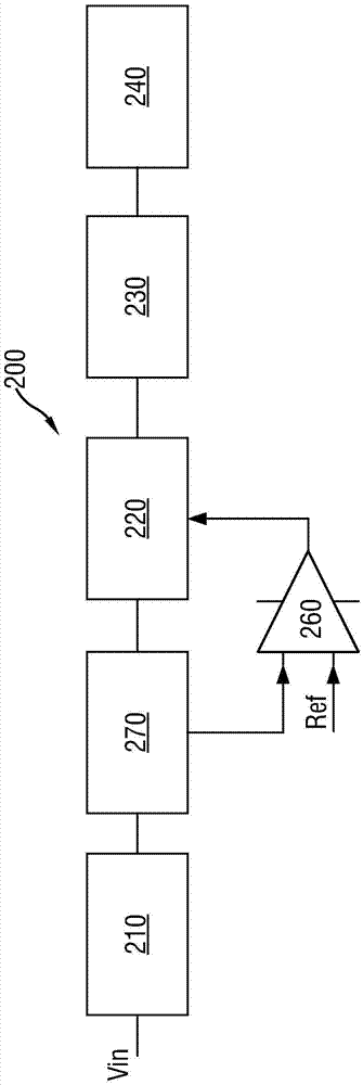
The invention provides a notification appliance in a fire fighting system and a method thereof. The notification appliance comprises an input end (210), a notification element (240), a boosting circuit (320), an energy storage circuit (230) an a control circuit (350), wherein the control circuit (350) sends a control signal (PWM) to the boosting circuit (320), the control signal indicates the duty ratio (D) of the boosting circuit (320) so as to enable the energy storage circuit (230) to periodically charge in the whole non-notification period (To) in general, wherein the duty ratio (D) is determined according to a value of input voltage (Vin) and a value (Ec) of energy to be stored into the storage circuit. A current limiting function can be realized without the need of an independent current limiting circuit by adopting the notification appliance.

Description

technical field [0001] The present invention generally relates to the field of fire alarming (Fire alarming), in particular to a notification device (Notification Appliance) capable of issuing a visual alarm (visual alarm) in a fire fighting system. Background technique [0002] figure 1 A schematic diagram of a typical fire alarm system is shown. Such as figure 1 As shown, in a fire alarm system, a fire alarm control device (Control Panel) 160 is connected to multiple fire detectors 170, notification devices 180, or manual alarms 190 distributed in the building. The fire detector 170, the notification device 180, and the manual alarm 190 may be collectively referred to as peripheral devices. These peripherals can be connected in parallel to a two-wire network that is connected to, and receives power from, the fire alarm control panel (Control Panel) 160 . exist figure 1 In the shown fire alarm system, the notification device 180, for example, can issue an audible alarm...

Claims


Application Information

Patent Timeline
Patent Type & Authority Applications(China)
IPC IPC(8): H02J7/00G08B7/06
CPCG08B7/06H02J7/00
Inventor 任瑞亭沈雪松谭建陈立国向阳
Owner SIEMENS SWITZERLAND
Learn More