Differential light beam image motion and scintillation laser radar turbulence profile real-time measuring method

A technology of laser radar and real-time measurement, which is applied in the direction of measuring devices, radio wave measurement systems, electromagnetic wave re-radiation, etc., can solve the problems of large instruments, inconvenient use, complex design, etc., and achieve simple instrument structure, improved versatility, High real-time effect

Inactive Publication Date: 2017-09-01
HEFEI INSTITUTES OF PHYSICAL SCIENCE - CHINESE ACAD OF SCI
View PDF4 Cites 12 Cited by
  • Summary
  • Abstract
  • Description
  • Claims
  • Application Information

AI Technical Summary

Problems solved by technology

However, its deficiencies or needs to be improved are also obvious: First, the existing differential beam radar needs to image the laser beam in a large height range, and must adopt a paraxial structure design, so the distance between the radar transmitting and receiving systems is relatively large, and the instrument too large
Secondly, the existing differential column image motion radar only extracts the beam jitter information of the turbulence effect after the laser beam passes through the atmosphere. The beam jitter is sensitive to low-altitude turbulence but not to high-altitude turbulence, and the error of directly using the jitter data to invert the turbulence profile is relatively lar

Method used


Image

  • Differential light beam image motion and scintillation laser radar turbulence profile real-time measuring method
  • Differential light beam image motion and scintillation laser radar turbulence profile real-time measuring method
  • Differential light beam image motion and scintillation laser radar turbulence profile real-time measuring method

Examples


Embodiment Construction

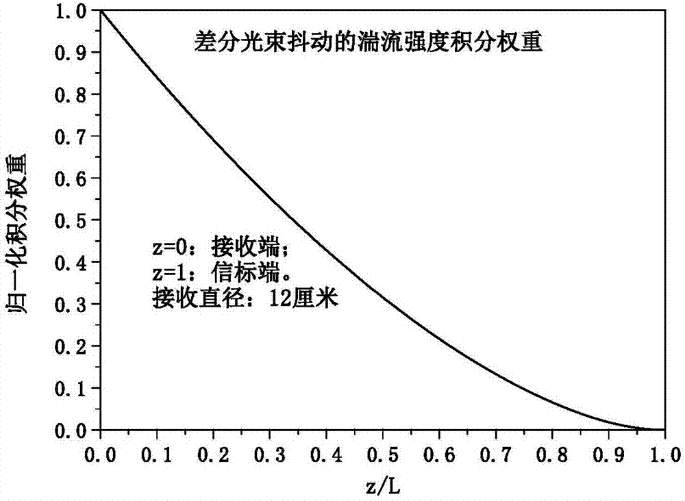
[0030] Such as figure 1 As shown, the method of real-time measurement of turbulence profile by differential beam image motion scintillation lidar, the designed laser emission system includes: laser 1, concave lens 2, convex lens 3, mirror pair 4,5. The laser light emitted by the laser 1 passes through the concave lens 2 and the convex lens 3 in turn, is reflected by the mirror pair 4, 5, and then enters the atmosphere along the optical axis of the telescope to form a laser beam beacon. The mirror pair 4 and 5 are installed in a quasi-parallel manner, and the angle between the two sets of mirrors can be fine-tuned. By fine-tuning the angle between the two sets of mirrors, the directivity of the laser can be fine-tuned, so that the emitted laser light is parallel to the optical axis of the receiving telescope 8. direction of emission.

[0031] Such as figure 1 As shown, the telescope receiving system of the present invention includes: a wedge mirror 6 , an aperture 7 , a...


PUM


Abstract

The invention discloses a differential light beam image motion and scintillation laser radar turbulence profile real-time measuring method. According to physical laws that intensity scintillation is sensitive to the intensity of atmospheric turbulence at a beacon end, and beam jitter is sensitive to turbulence at a receiving end, the invention adopts a method for carrying out simultaneous statistics on intensity scintillation and beam jitter information of a laser beacon obtained after passing through atmosphere; through differentiate operation, a pair of parameters sensitive to the beacon-end turbulence and the receiving-end turbulence can be obtained; and therefore, influence of laser upward transmission, apparatus jitter or inherent scintillation of laser on measurement can be eliminated, and interference of turbulence randomicity on measurement is reduced. On the basis above, the method adopts a double-exponential model of turbulence intensity to describe finite-height turbulence intensity height distribution; according to physical meanings of each exponential term in the model, experience statistical value of coefficient of one exponential term is adopted, and inversion is carried out in real time to obtain coefficient of another exponential term; and through real-time-measurement differential flutter and differential scintillation exponential term coefficient inversion, turbulence intensity height distribution data can be obtained in real time.

Description

technical field [0001] The invention relates to the field of turbulent flow profile measurement methods, in particular to a method for real-time measurement of turbulent flow profile by differential beam image movement and scintillation laser radar. Background technique [0002] At present, an advanced method to obtain the turbulence profile of the whole layer in real time is to use the differential column image motion lidar together with the equihalation angle measuring instrument, and use the differential column image motion lidar to image the laser beam at a height range of several kilometers and extract the beam The atmospheric coherence length profile is obtained from the differential jitter information of the star, and the iso-halo angle is obtained by measuring the scintillation effect of the star after passing through the atmosphere with the iso-halo angle measuring instrument, and the refractive index structure constant profile is obtained by combining the three-expo...

Claims


Application Information

Patent Timeline
IPC IPC(8): G01W1/08G01S17/95
CPCG01S17/95G01W1/08Y02A90/10
Inventor 靖旭王英俭何枫谭逢富秦来安张巳龙张守川侯再红吴毅
Owner HEFEI INSTITUTES OF PHYSICAL SCIENCE - CHINESE ACAD OF SCI
Why Eureka
Try Eureka