Drilling structure and construction method thereof

A construction method and annular buffer technology, applied in drill pipe, drill pipe, earth-moving drilling, etc., can solve problems such as easy damage of drilling holes, and achieve the effect of improving the stability of drilling holes

Active Publication Date: 2017-09-01
XINJIANG GUOLIHENG CLEAN ENERGY TECH CO LTD
View PDF10 Cites 3 Cited by
  • Summary
  • Abstract
  • Description
  • Claims
  • Application Information

AI Technical Summary

Problems solved by technology

[0005] In view of this, the present invention proposes a kind of, aims at solving the problem that existing borehole is easily damaged

Method used


Image

  • Drilling structure and construction method thereof
  • Drilling structure and construction method thereof
  • Drilling structure and construction method thereof

Examples


Embodiment Construction

[0024] Exemplary embodiments of the present disclosure will be described in more detail below with reference to the accompanying drawings. Although exemplary embodiments of the present disclosure are shown in the drawings, it should be understood that the present disclosure may be embodied in various forms and should not be limited by the embodiments set forth herein. Rather, these embodiments are provided for more thorough understanding of the present disclosure and to fully convey the scope of the present disclosure to those skilled in the art. It should be noted that, in the case of no conflict, the embodiments of the present invention and the features in the embodiments can be combined with each other. The present invention will be described in detail below with reference to the accompanying drawings and examples.

[0025] Examples of drilling structures:

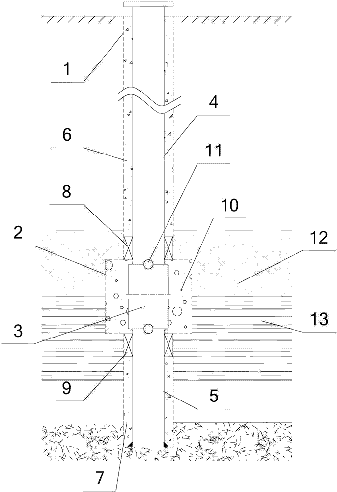
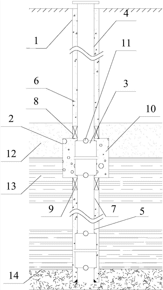
[0026] see figure 1 and figure 2 , the drilling structure may include: a drilling body 1 , an annular buffer zon...


PUM


Abstract

The invention provides a drilling structure. The drilling structure comprises a drilling body, an annular buffer zone and a stress compensator, wherein the annular buffer zone is arranged on a first preset position of the drilling body, and the diameter of the annular buffer zone is bigger than the diameter of the drilling body. The stress compensator is arranged in the annular buffer zone, and a first casing pipe and a second casing pipe are correspondingly arranged at the positions, above and below the stress compensator, in the drilling body in a sleeving mode. According to the drilling structure, not only is intensity of a shear stress reduced through the arranged annular buffer zone, but also the stress compensator can be stretched to a certain length when stress exceeds the permissible value of a compensator through the arranged stress compensator, thus tensile failure to the first casing pipe and the second casing pipe from the excessive stress is compensated, stretch and shearing load caused by ground movement is counteracted by the stress compensation, the drilling is enabled to adapt to changes of rock stratum, drilling stability is improved, and the damage of drilling in the underground gasification process and further influence to coal gasification are avoided.

Description

technical field [0001] The invention relates to the technical field of coal and coalbed methane mining, in particular to a drilling structure and a construction method thereof. Background technique [0002] Underground coal gasification technology is a technology that utilizes in-situ combustion and gasification reactions of coal to produce coal gas or synthetic gas. Boreholes and corresponding gasification passages connecting the inlet and outlet holes. Generally, the air inlet borehole is used to deliver gasification agent (such as air, oxygen, etc.) The air outlet borehole is discharged to the ground for subsequent use. The borehole connects the ground and the underground, and the stability of the borehole is one of the keys to the success of underground gasification. [0003] In the process of underground coal gasification, the coal seam combustion provides the energy required for the gasification reaction, and the combustion void zone is formed in the coal seam due t...

Claims


Application Information

Patent Timeline
IPC IPC(8): E21B17/00E21B43/295
CPCE21B17/00E21B43/295
Inventor 徐斌张树川郑林杜慧华徐军
Owner XINJIANG GUOLIHENG CLEAN ENERGY TECH CO LTD
Why Eureka
Try Eureka