An inclined surface laminating mechanism and a concrete box girder spreader

A technology of concrete box girders and inclined planes, applied in the direction of load hanging components, transportation and packaging, etc., can solve the problems of increased manpower and material resources expenditure, small contact area, complicated operation, etc., to improve hoisting safety, uniform pressure distribution, and simplified The effect of lifting steps

Active Publication Date: 2018-02-06
SHANDONG RUIHONG HEAVY IND MACHINERY CO LTD
View PDF5 Cites 0 Cited by
  • Summary
  • Abstract
  • Description
  • Claims
  • Application Information

AI Technical Summary

Problems solved by technology

The premise of this hoisting method is that there must be enough space between the prefabricated concrete box girder and the ground for the wire rope to pass through, otherwise it is very difficult to bind the prefabricated concrete box girder; Shaking is inevitable, the steel wire rope and the concrete prefabricated box girder are squeezed, slid, and misplaced, and the contact area between the steel wire rope and the concrete prefabricated box girder is small, and the pressure is too concentrated, which can easily cause damage to the concrete prefabricated box girder Or wear off the strands of the wire rope, which will bring safety hazards
[0003] The existing concrete prefabricated box girder hoisting gear is the same as the steel wire rope hoisting principle. Before hoisting, a part of the hoisting gear needs to be placed at the bottom of the concrete prefabricated box girder, so as to further lift the concrete prefabricated box girder to realize hoisting; however, This hoisting method is complicated to operate, and the operation of placing the spreader on the bottom of the concrete prefabricated box girder itself is quite difficult, and usually requires the cooperation of other large-scale lifting machinery to complete the operation, which increases unnecessary manpower and material resources.

Method used


Image

  • An inclined surface laminating mechanism and a concrete box girder spreader
  • An inclined surface laminating mechanism and a concrete box girder spreader
  • An inclined surface laminating mechanism and a concrete box girder spreader

Examples


Embodiment Construction

[0015] The specific implementation manners of the present invention will be described in further detail below in conjunction with the accompanying drawings.

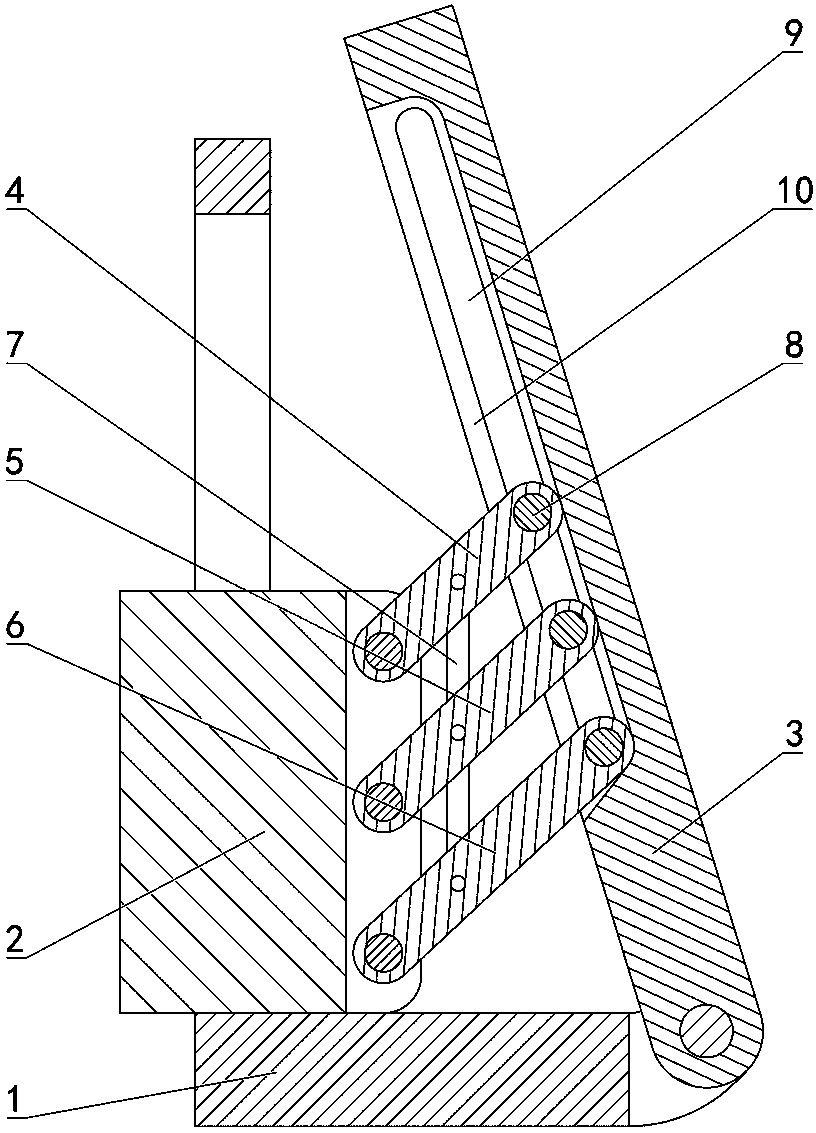
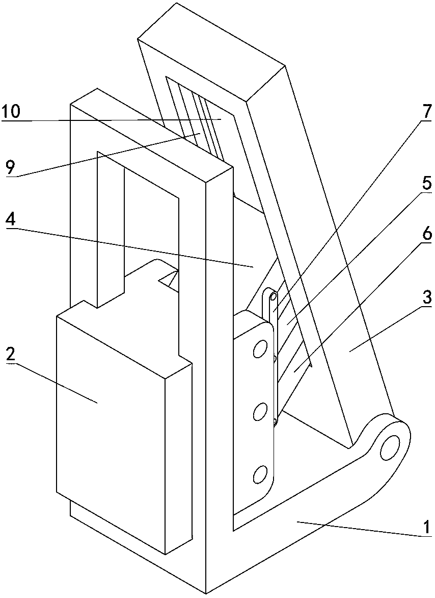
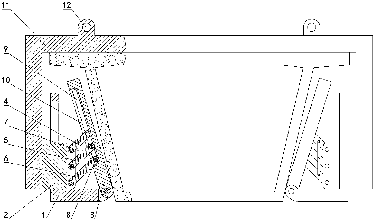
[0016] combine Figure 1 to Figure 4 , the present invention provides a kind of bevel fitting mechanism, including a base 1 arranged horizontally, the left end of the base 1 is installed with a connecting block 2 that is above the base 1 and can slide vertically on the base 1, the base The right end of 1 is hinged with an extrusion plate 3 inclined to the left;

[0017] The first connecting rod 4, the second connecting rod 5 and the third connecting rod 6 placed on the right side of the connecting block 2 and parallel to each other are arranged on the connecting block 2, and the first connecting rod 4, the second connecting rod 5 and the The left end of the third connecting rod 6 is hinged on the right end of the connecting block 2, and the right side of the connecting block 2 has a vertical rod 7, and the vertical rod ...


PUM


Abstract

The invention relates to a slope joint mechanism and a concrete box girder lifting appliance. A connecting block is installed at the left end of a base in a vertically sliding mode. An extrusion plate is hinged to the right end of the base. The connecting block is provided with a first connecting rod, a second connecting rod and a third connecting rod which are parallel to one another. The left ends of the connecting rods are hinged to the right end of the connecting block. A vertical rod is arranged on the right side of the connecting block and hinged to the first connecting rod, the second connecting rod and the third connecting rod at the same time. The right ends of the first connecting rod, the second connecting rod and the third connecting rod are provided with longitudinally arranged rotating shafts. The extrusion plate is provided with a sliding groove, and the rotating shafts are arranged in the sliding groove. A downward acute angle is reserved between the third connecting rod and the extrusion plate. The concrete box girder lifting appliance comprises two slope joint mechanisms arranged symmetrically, wherein the two slope joint mechanisms are connected through a supporting beam, the two ends of the supporting beam are connected with the connecting blocks correspondingly, and the extrusion plates are arranged below the supporting beam. The slope joint mechanism and the concrete box girder lifting appliance are ingenious in structure and convenient to operate.

Description

technical field [0001] The invention relates to the field of hoisting of prefabricated concrete box girders, in particular to an inclined surface fitting mechanism and a concrete box girder hanger. Background technique [0002] When the concrete prefabricated box girder is hoisted, because the concrete prefabricated box girder is large and difficult to fix, it is usually bound with steel wire ropes and then lifted by hoisting equipment. The premise of this hoisting method is that there must be enough space between the prefabricated concrete box girder and the ground for the wire rope to pass through, otherwise it is very difficult to bind the prefabricated concrete box girder; Shaking is inevitable, the steel wire rope and the concrete prefabricated box girder are squeezed, slid, and misplaced, and the contact area between the steel wire rope and the concrete prefabricated box girder is small, and the pressure is too concentrated, which can easily cause damage to the concret...

Claims


Application Information

Patent Timeline
Patent Type & Authority Patents(China)
IPC IPC(8): B66C1/28
CPCB66C1/28B66C1/30B66C1/42
Inventor 丛卫国张超王猛王强刘学
Owner SHANDONG RUIHONG HEAVY IND MACHINERY CO LTD
Why Eureka
Try Eureka