
Device of fuel injection system and metal-to-metal sealing connection arrangement

A technology for connecting components and metal seals, which is applied in the direction of fuel injection devices, special fuel injection devices, mechanical equipment, etc., can solve the problems of pre-tightening force not being determined to a large extent, large deviation of sealing position, and large safety factor, etc., to achieve The effect of reducing material usage, improving sealing effect, and increasing power density

Active Publication Date: 2017-08-29
ROBERT BOSCH GMBH
View PDF18 Cites 0 Cited by
  • Summary
  • Abstract
  • Description
  • Claims
  • Application Information

AI Technical Summary

Problems solved by technology

[0003] The rail assembly known from DE 10 2008 035 492 A1 and the connection provided here by means of an axial press-in configuration have the disadvantage that the pretensioning forces occurring on the connection are not determined to a large extent
However, the problem arises here that due to torque-controlled assembly large deviations in the behavior of the sealing position can occur due to various influences
This is particularly disadvantageous, because in order to ensure minimum deformation or preload force, a very large safety factor must be applied when designing the connection partner

Method used


Image

  • Device of fuel injection system and metal-to-metal sealing connection arrangement
  • Device of fuel injection system and metal-to-metal sealing connection arrangement
  • Device of fuel injection system and metal-to-metal sealing connection arrangement

Examples


Embodiment Construction

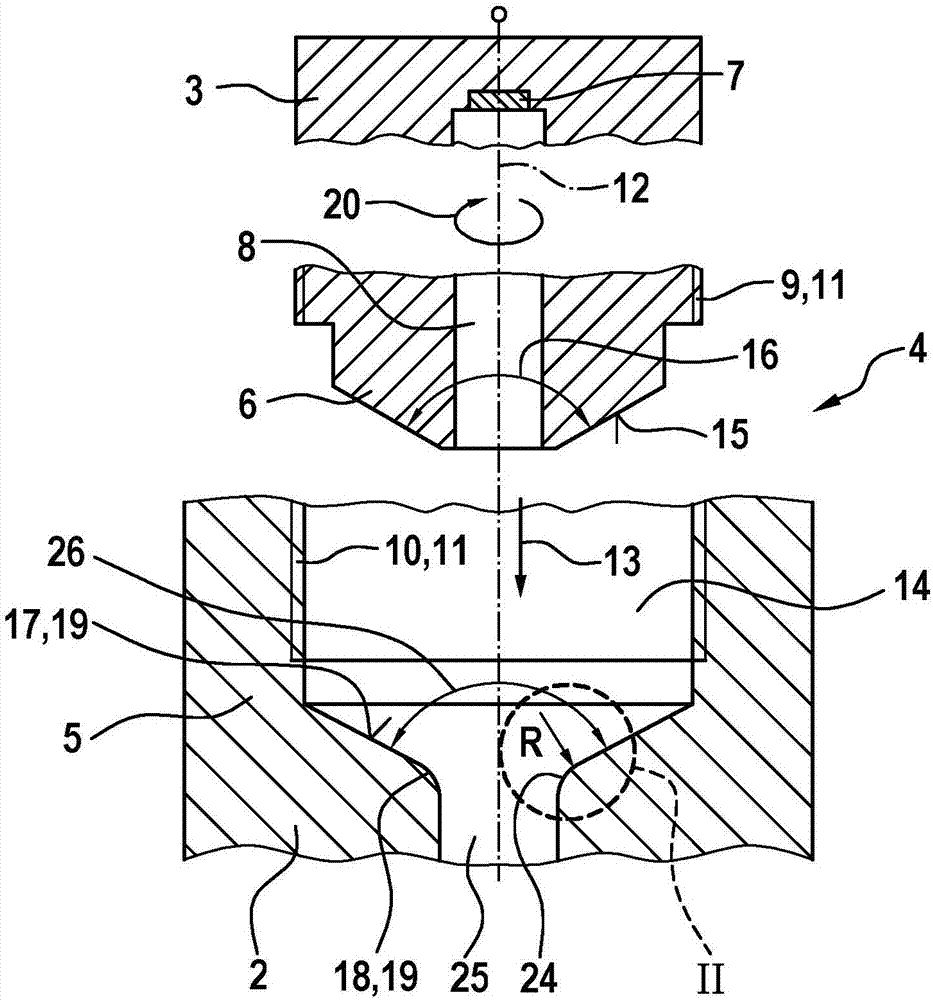
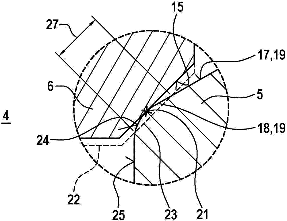
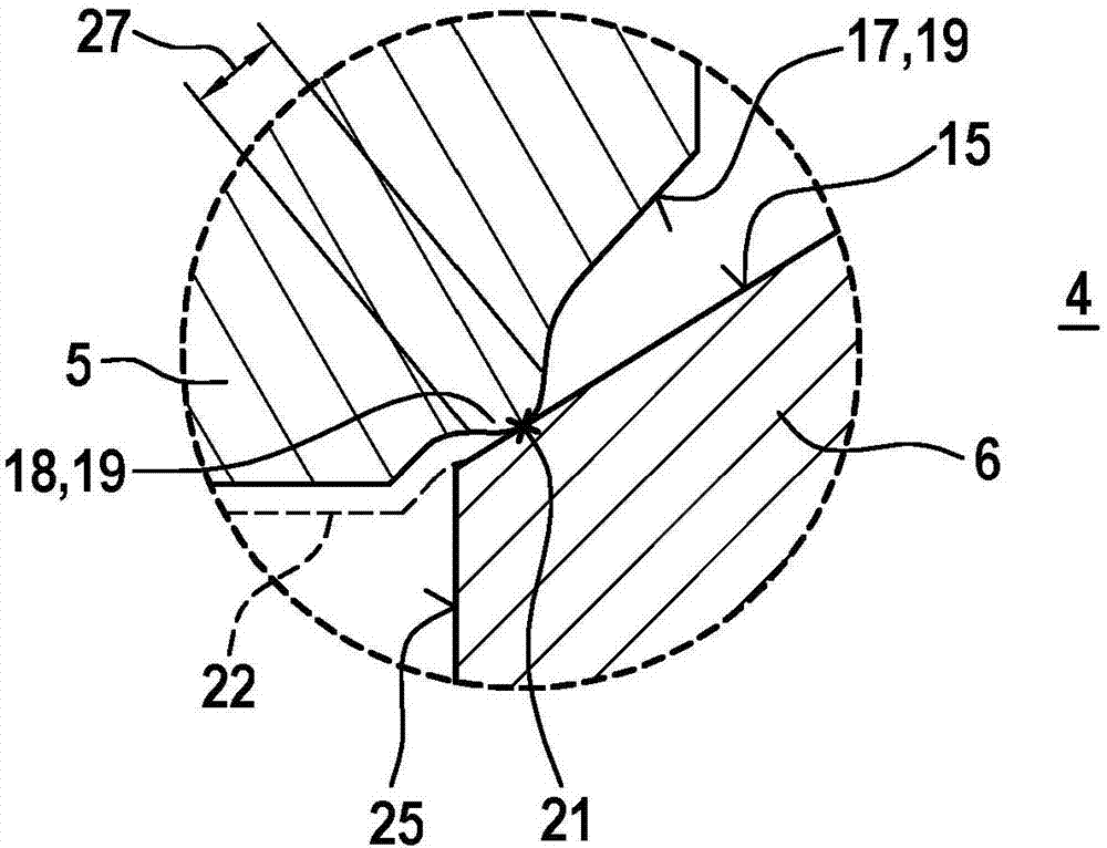
[0022] figure 1 shows a device 1 of a fuel injection system with a fuel-conducting part 2 and a connection part 3 , wherein the connection assembly 4 can be built on a connection partner 5 arranged on the part 2 and a connection partner arranged on the connection part 3 between 6. here, figure 1 In a simplified schematic sectional view corresponding to the first exemplary embodiment, the connection assembly 4 is shown in the state before assembly, in which state the connection partner 6 on the connection part 3 serves as the first connection partner 6, and on the part 2 The upper connection partner 5 serves as the second connection partner 6 .

[0023] The component 2 can be designed in particular as a fuel distribution rail 2 . The connecting piece 3 can be designed as a sensor 3 . For this purpose, a sensor element 7 can be provided which, in the assembled state, measures the fuel pressure present, for example, in the axial bore 8 of the connecting part 3 . The connecti...


PUM


Abstract

A device (1) of a fuel injection system has a fuel-conducting component (2) and a connecting part (3). A metal-to-metal sealing connection arrangement (4) is provided which comprises a first metal connection partner (6) and a second metal connection partner (5). The metal connection partners (5, 6) can be connected to each another with respect to an axis (12), with a conical sealing surface (15) on the first connection partner (6) and a sealing contour (19) matching the conical sealing surface (15) of the first connection partner (6) on the second connection partner (5). The sealing contour (19) of the second connection partner (5) has, in an initial state, a circumferential elevation (18) around the axis (14), said elevation facing the conical sealing surface (15) of the first sealing partner (6), wherein the sealing contour (19) of the second connection partner (5) is configured such that, with the screwing of the first connection partner (6) to the second connection partner (5), the circumferential elevation (18) of the second connection partner (5) is at least partially plastically deformed, in order to form a metal-to-metal seal between the conical sealing surface (15) of the first connection partner (6) and the elevation (18) of the second connection partner (5) that is deformed in the screwed state.

Description

technical field [0001] The invention relates to a metal-tight connection assembly and to an arrangement of a fuel injection system having the metal-tight connection assembly. The invention relates in particular to the field of fuel injection systems for internal combustion engines. Background technique [0002] A rail arrangement for a fuel injection system is known from DE 10 2008 035 492 A1. The rail assembly is used in particular for an internal combustion engine of a motor vehicle. In this case, a supply line is provided for conveying and supplying fuel under pressure, and a plurality of branches fastened to the supply line are provided for fluidly connecting the supply line to a fuel injector in each case. Furthermore, at its axial end, the supply pipe has an inner contour, into which the pressure sensor connection is plugged, which is conical in shape complementary to the outer contour of the use section. Here too, the conical inner contour with an outwardly widenin...

Claims


Application Information

Patent Timeline
IPC IPC(8): F02M55/00F02M55/02
CPCF02M55/004F02M55/025F02M2200/9053F02M2200/247
Inventor K·朗G·赫克N·席尔霍尔茨
Owner ROBERT BOSCH GMBH
Learn More