
container for paste

A technology for paste and container, which is applied in the field of containers, can solve the problem that it is difficult for the contents to be placed on a toothbrush, etc., and achieve the effect of convenient use.

Inactive Publication Date: 2018-12-07
LION CORP
View PDF11 Cites 0 Cited by
  • Summary
  • Abstract
  • Description
  • Claims
  • Application Information

AI Technical Summary

Problems solved by technology

Therefore, for example, in the tube container that accommodates the dentifrice, it is sometimes difficult to place the discharged contents on the toothbrush.

Method used


Image

  • container for paste
  • container for paste
  • container for paste

Examples


Embodiment Construction

[0035] The following definitions of terms apply to this specification and claims.

[0036] "Engaged state" refers to a state in which two engaging parts (for example, protrusion and groove, protrusion and protrusion, etc.) engage with each other to restrict movement in a specific direction through fitting, locking, abutting, or the like.

[0037] "Above" refers to the direction from the bottom of the container body toward the upper cover portion of the cap, and "upper end" refers to the end in the above direction.

[0038] "Downward" refers to the direction from the upper part of the cap toward the bottom of the container body, and "lower end" refers to the end in the above direction.

[0039] "Up and down directions" refer to both directions of up and down.

[0040] A "hinge" refers to a mechanism provided at a junction of two parts and capable of rotating the two parts around a rotation axis. Examples of the rotating shaft include a bendable thin-walled portion, a column, ...


PUM


Abstract

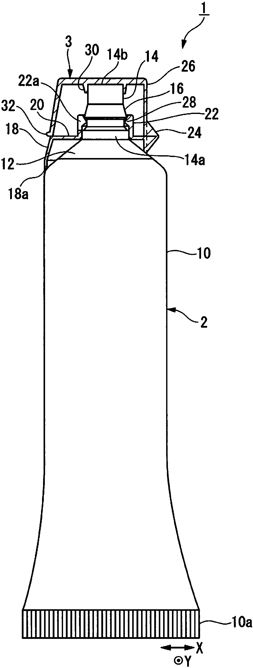
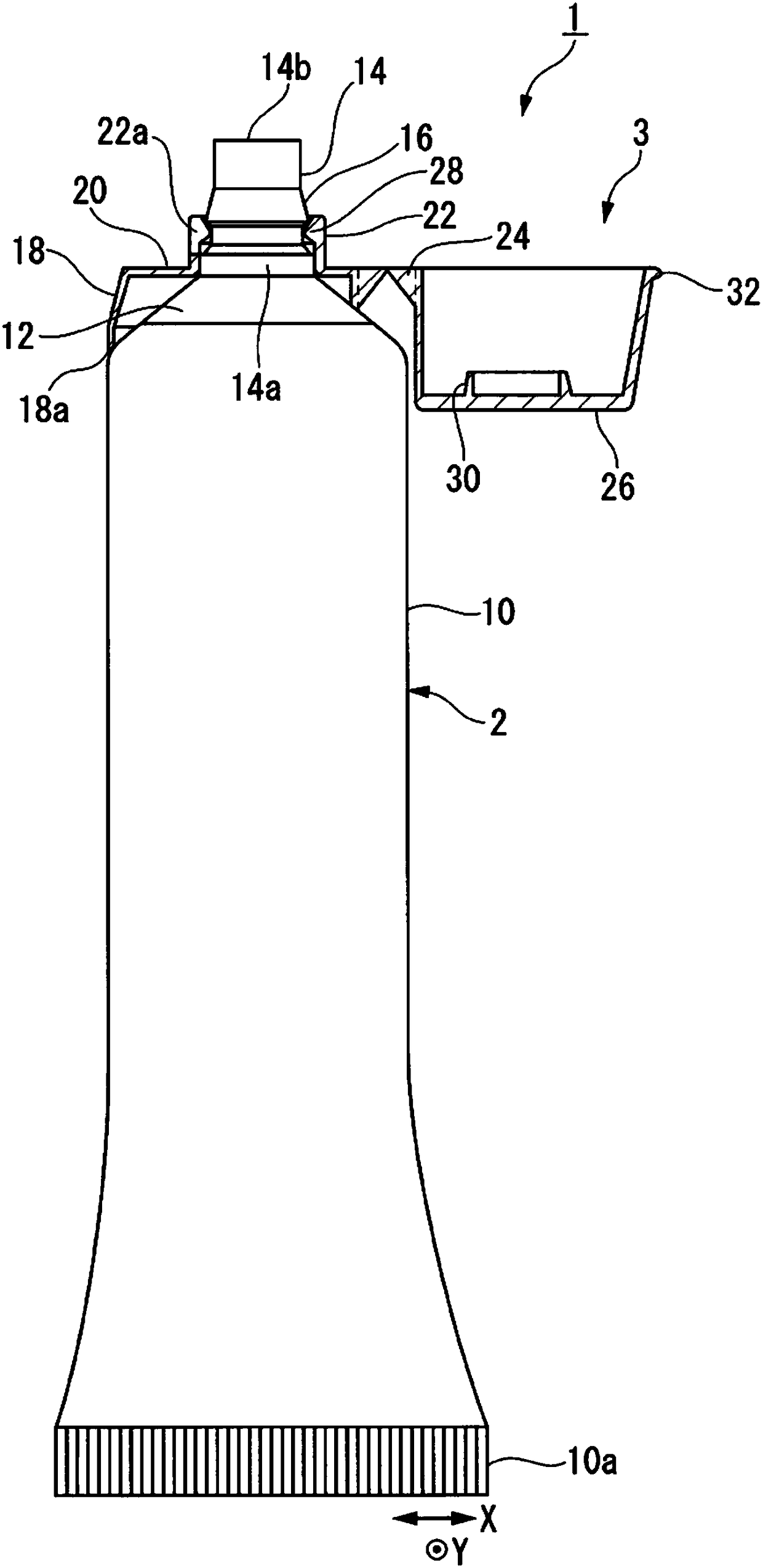
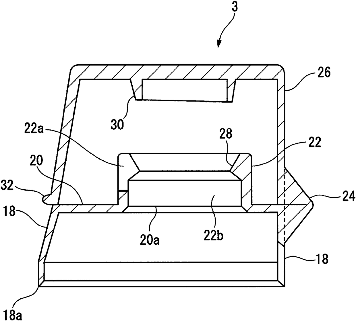
Provided is a container configured so that the user can select a method for opening the container according to their preferences, can completely use up the contents, and can easily handle the container when pouring out the contents. A container (1) is provided with: a container body (2) having a shoulder (12) and a neck (14) which is open at the upper end; and a cap (3) configured so that an upper plate (20) extends inward from the upper end of an outer cylinder wall (18), a protruding cylinder (22) extends upward from the inner peripheral edge of the upper plate, and the cap (3) is provided with an upper lid (26) connected to the upper plate (20) through a hinge (24). The upper end-side portion of the neck (14) protrudes upward from a through-hole in the upper plate (20) while the cap (3) is mounted to the container body (2), the through-hole being formed in the upper plate (20). An engagement structure is formed by a first engagement section (16) which is provided to the neck (14) and by a second engagement section (28) which is provided to the protruding cylinder (22). When facing portions of the outer cylinder wall (18) are pressed inward radially, the lower end (18a) of the outer cylinder wall (18) comes into contact with the shoulder (12) and rises, and thus the engagement structure is disengaged.

Description

technical field [0001] The present invention relates to a container. [0002] This application claims priority based on Japanese Patent Application No. 2014-260413 for which it applied in Japan on December 24, 2014, and uses the content here. Background technique [0003] A hinged cap is known as a cap in a tube container for storing dentifrice or a bottle container for storing cosmetics or the like. As a specific example of the hinged lid, the following lid can be enumerated: the lower end of the cylindrical outer cylinder wall is fixed to the upper end of the container main body by a push-in type fitting, and is set to close the upper end of the above-mentioned outer cylinder wall, In addition, the top plate portion having a discharge port for discharging the contents is formed in the central portion, and an upper cover portion for closing the discharge port is provided through a hinge portion. The container provided with the hinged lid is excellent in usability because ...

Claims


Application Information

Patent Timeline
Patent Type & Authority Patents(China)
IPC IPC(8): B65D35/44
CPCB65D35/44
Inventor 加藤启育铃木真吾
Owner LION CORP
Learn More