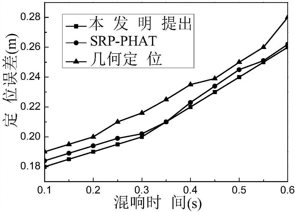
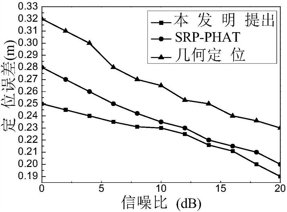
Sound source positioning system based on distributed microphone array
A technology for microphone array and sound source localization, which is used in localization, radio wave measurement systems, measurement devices, etc., and can solve problems such as limited microphone array topology
Active Publication Date: 2017-08-29
DALIAN UNIV OF TECH
View PDF4 Cites 57 Cited by
- Summary
- Abstract
- Description
- Claims
- Application Information
AI Technical Summary
Problems solved by technology
But this method is limited by the topology of the microphone array
Method used
View moreImage
Smart ImageViewing Examples
Examples
Embodiment 1
Login to View More PUM
 Abstract
The invention discloses a sound source positioning system based on a distributed microphone array, and the system comprises a preprocessing unit which carries out the frame dividing of a signal according to an initial audio signal collected by a microphone subarray, analyzes and calculates the short-time energy of each frame of the audio signal, obtains the noise frame and voice frame in an audio frame sequence, and obtains the signal to noise ratio of the audio frame sequence; a subarray selection unit which analyzes the direct-reverse ratio (DRR) of the signal received by each subarray of the microphone array, and selects the microphone subarray with the DRR being greater than a threshold value; a time delay calculation unit; a sound source positioning unit which carries out the pre-estimation of the position of the sound source according to the time delay of each microphone pair, and obtains a rough positioning module of a sound source space U; a precise positioning module which carries out the searching in the sound source space U, and obtains the maximum point of the improved controllable response power in the sound source space U. The system analyzes the positioning result of the plurality of microphone subarrays, and finally determines the position of the sound source through consistency processing.
Description
A sound source localization system based on distributed microphone array technical field The invention relates to a sound source localization system based on a distributed microphone array. Involving Patent Classification G Physics G01 Measurement; Test G01S Radio Orientation; Radio Navigation; Ranging or Velocity Measurement Using Radio Waves; Positioning or Presence Detection Using Reflection or Re-radiation of Radio Waves; Similar Devices Using Other Waves G01S5 / 00 Pass Determination To locate by the fit of two or more directions or lines of position; to locate by the fit of two or more distances. Background technique In recent years, the topic of artificial intelligence has become extremely hot, and it has shown a ubiquitous trend in people's lives. In the "Internet of Things Era", voice plays a pivotal role in human-computer interaction. Over the past few years, speech signal processing methods based on distributed microphone arrays have gradually become a new resea...
Claims
Login to View More Application Information
Patent Timeline
 IPC IPC(8): G01S5/22
CPCG01S5/22
Inventor 陈喆殷福亮卢艳美
Owner DALIAN UNIV OF TECH
- R&D Engineer
- R&D Manager
- IP Professional
- Industry Leading Data Capabilities
- Powerful AI technology
- Patent DNA Extraction
Learn More Browse by: Latest US Patents, China's latest patents, Technical Efficacy Thesaurus, Application Domain, Technology Topic, Popular Technical Reports.
© 2024 PatSnap. All rights reserved.Legal|Privacy policy|Modern Slavery Act Transparency Statement|Sitemap|About US| Contact US: help@patsnap.com


