Eureka AIR delivers breakthrough ideas for toughest innovation challenges, trusted by R&D personnel around the world.

Sound source positioning following system and method based on microphone array

A microphone array and sound source localization technology, which is applied in the direction or offset system, positioning, radio wave measurement system and other directions, and can solve the problems of immature application technology

Inactive Publication Date: 2017-05-31
深圳市行者机器人技术有限公司
View PDF3 Cites 16 Cited by
  • Summary
  • Abstract
  • Description
  • Claims
  • Application Information

AI Technical Summary

Problems solved by technology

Although the speech processing technology based on the microphone array is becoming a new research hotspot, the relevant application technology is not yet mature

Method used


Image

  • Sound source positioning following system and method based on microphone array
  • Sound source positioning following system and method based on microphone array
  • Sound source positioning following system and method based on microphone array

Examples


Embodiment 1

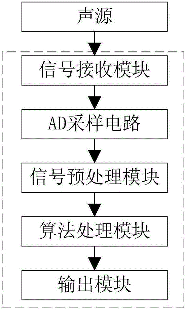
[0085] As shown in the figure, the microphone array-based sound source location following system provided by this embodiment includes a signal receiving module, an AD sampling circuit, a signal preprocessing module, an algorithm processing module and an output module;

[0086] The signal receiving module is a microphone array, which is used to obtain voice signals from the sound source to each microphone;

[0087] The AD sampling circuit is used to obtain the voice sampling signal of each microphone;

[0088] The signal preprocessing module is used to preprocess the voice sample signal;

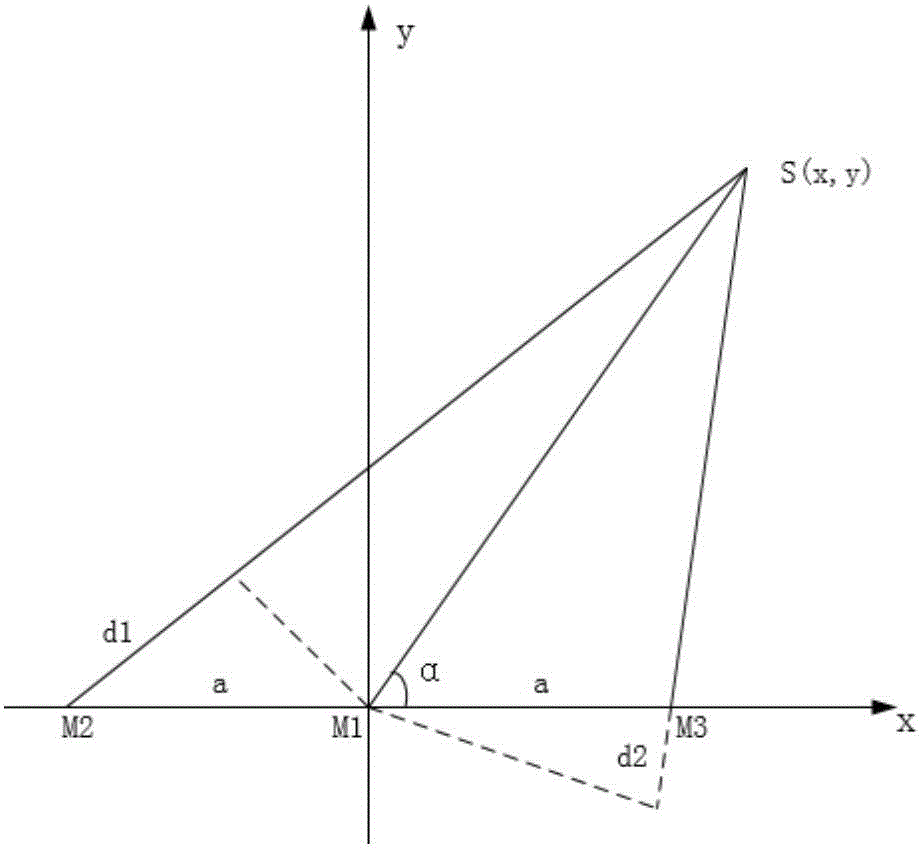
[0089] The algorithm processing module is used to calculate the sound source position according to the voice sampling signal;

[0090] The output module is used to output sound source location information.

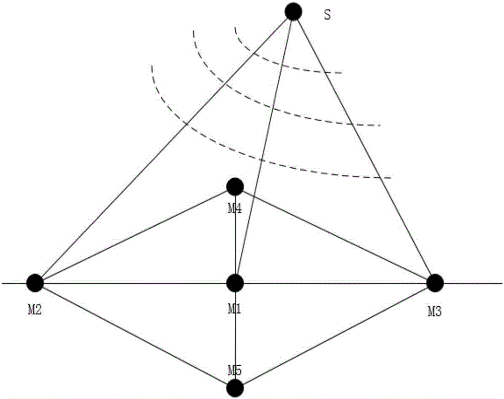
[0091] The microphone array includes a uniform linear subarray A, a uniform linear subarray B and a reference point microphone perpendicular to each other; .

[0092] The signal prepr...

Embodiment 2

[0138] The sound source positioning and following method based on the microphone array provided in this embodiment uses a handheld device and a sound source carried by a walking device to form a positioning system for positioning. The positioning system is set on a walking device, such as a walking aid and a walking aid wheelchair, such figure 1 As shown in the dotted line box in the middle, the dotted line box represents the walking device, and wireless communication is established through Bluetooth. When the handheld device sends out a sound source signal, it triggers the positioning system to start sampling. When the handheld device sends out no sound source signal, the positioning system turns off. In this way, real-time positioning and following of the walking device can be realized. In the case of close-distance follow-up of the walking device, the position of the sound source can be accurately determined, the real-time performance is strong, and the algorithm is simple a...


PUM


Abstract

The invention discloses a sound source positioning following system and method based on a microphone array, and the system comprises a signal receiving module, an AD sampling circuit, a signal preprocessing module, an algorithm processing module, and an output module. The signal receiving module is the microphone array, and is used for obtaining the voice signal transmitted to each microphone from the sound source. The AD sampling circuit is used for obtaining the voice sampling signals of all microphones. The signal preprocessing module is used for the preprocessing of the voice sampling signals. The algorithm processing module is used for calculating the position of the sound source according to the voice sampling signals. The output module is used for outputting the position information of the sound source. The system builds the wireless communication through a Bluetooth, obtains the sound source signals, determines the position of the sound source signals, and can achieve the real-time positioning and following of a walking device. The system can accurately locate the sound source under the condition that the walking device follows at a short distance, is high in instantaneity, is simple in algorithm, and is easy to implement.

Description

technical field [0001] The invention relates to the field of voice signal processing, in particular to a sound source localization and following system and method based on a microphone array. Background technique [0002] As early as the 1970s and 1980s, microphone arrays were used in the research of speech signal processing. Since the 1990s, speech signal processing algorithms based on microphone arrays have gradually become a new research hotspot. In 1995 flanagan used array signal processing to capture sound in a reverberant environment. In 1996, silverman and brandstein began to apply it to sound source localization, which is used to determine and track the speaker's position in real time. [0003] At present, the microphone array system has been used in many occasions, including video conferencing, speech recognition, speaker recognition, car environment voice acquisition, reverberation environment sound pickup, sound source localization and hearing aids, etc. Althoug...

Claims


Application Information

Patent Timeline
IPC IPC(8): G10L21/0272G10L21/0216G01S5/20G01S3/808
CPCG10L21/0272G01S3/8083G01S5/20G10L21/0216G10L2021/02166
Inventor 朱静波
Owner 深圳市行者机器人技术有限公司
Why Eureka
Eureka Blog
Learn More