
Oil well pressure recovery testing device and system

A technology for restoring test and pressure, applied in the direction of measuring devices, instruments, etc., can solve the problems of cumbersome operation, polluted well site, and bulky equipment, etc., to achieve the effect of increasing the air intake area

Pending Publication Date: 2017-08-29
SHENYANG SENSOR TECH
View PDF4 Cites 1 Cited by
  • Summary
  • Abstract
  • Description
  • Claims
  • Application Information

AI Technical Summary

Problems solved by technology

[0003] However, the currently widely used on-site instruments and equipment for monitoring liquid level depth and casing pressure changes are bulky, cumbersome to operate, and have poor rainproof and anti-theft performance. During the test, nitrogen cylinders and batteries need to be replaced, and damage to the instrument due to oil filling often occurs, which is even more serious. The most important thing is that oil injection during the instrument test sometimes pollutes the well site and even pollutes the surrounding environment, causing serious environmental protection incidents
The main problem is: to complete a test, the instrument generally needs to be installed in the field well site for at least seven days. Traditional instruments and test methods cannot grasp the test situation on site during this test period, which often results in test failures, data errors, The oil filling of the instrument and the pollution of the well site have seriously affected the work efficiency and test results

Method used


Image

  • Oil well pressure recovery testing device and system
  • Oil well pressure recovery testing device and system

Examples


Embodiment 1

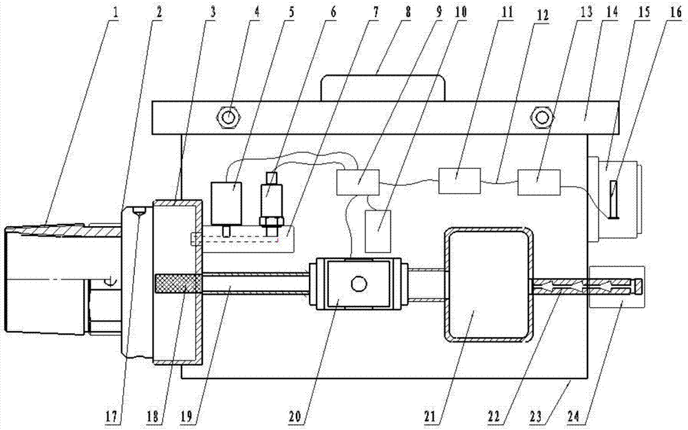
[0028] Such as figure 1 As shown, the oil well pressure recovery testing device of the present embodiment includes a box body 23, a box cover 14 and an oil-gas cavity 3 pierced on the side wall of the box body 23. The box cover 14 is provided with a handle 8, and the box cover 14 passes through the The plum blossom anti-theft screw 4 is installed on the box body 23, and the box body 23 is provided with a deflation unit and a control unit;

[0029]The deflation unit includes an airway pipeline 19 , a deflation solenoid valve 20 , a buffer tank 21 and an exhaust muffler 22 connected in sequence. Wherein the airway pipeline 19 communicates with the oil-gas chamber 3, and a barrel-type, 150-mesh filter 18 is buckled at the connection between the oil-gas chamber 3 and the airway pipeline 19. The filter screen 18 is located in the oil-gas chamber 3 and is different from the airway pipeline 19. One side of the filter screen 18 is sprayed with an anti-corrosion coating to enhance the...


PUM


Abstract

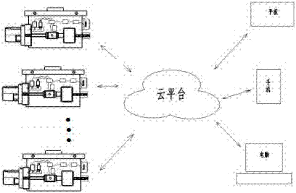
The present invention discloses an oil well pressure recovery testing device. The device comprises a case body, a case cover and an oil gas cavity passing through the side wall of the case body, the case body is internally provided with a venting unit and a control unit; the venting unit comprises an airway pipeline and a venting solenoid valve which are communicated with each other, and the oil gas cavity is communicated with the airway pipeline; the control unit comprises a controller and a microphone, a power supply and a wireless communication module which are electrically connected with the controller, the microphone is arranged on a microphone adapter piece fixed on the oil gas cavity; and the venting unit is electrically connected with the controller, the outer wall of the case body is provided with an antenna, and the antenna is electrically connected with the wireless communication module. The present invention further discloses an oil well pressure recovery testing system comprising a plurality of oil well pressure recovery testing devices, the system comprises a cloud platform connected with the oil well pressure recovery testing device and a plurality of control terminals connected with the cloud platform. The oil well pressure recovery testing device and system can realize remote monitoring of the oil well pressure recovery test.

Description

technical field [0001] The invention relates to the technical field of pressure recovery testing, in particular to a device and system for realizing pressure recovery testing of oil wells by monitoring changes in liquid surface depth and casing pressure. Background technique [0002] The pressure recovery test is to understand the change trend of the formation pressure with time from the shutdown of the oil well in normal production. The pressure recovery test is the most commonly used unstable well test technology in the pressure recovery test. This technology is widely used in the petroleum industry. Oil well pressure recovery test with liquid level monitor is the most commonly used and most effective method in unstable well test. It has been widely used in various oil fields and has gradually replaced the costly downhole pressure gauge test mode. [0003] However, the currently widely used on-site instruments and equipment for monitoring liquid level depth and casing pres...

Claims


Application Information

Patent Timeline
IPC IPC(8): G01D21/02
CPCG01D21/02
Inventor 陈明陆森平赵美焦李常雷
Owner SHENYANG SENSOR TECH
Learn More