Fluid mixing mechanism

A technology of fluid mixing and mixing tubes, which is applied in the direction of mixers, fluid mixers, mixing methods, etc., and can solve problems such as solidification and blockage

Active Publication Date: 2017-08-29
GUANGZHOU YONGHEXIANG AUTOMATION EQUIP TECH CO LTD
View PDF2 Cites 2 Cited by
  • Summary
  • Abstract
  • Description
  • Claims
  • Application Information

AI Technical Summary

Problems solved by technology

However, when the fluid mixing mechanism is used to make coagulating mixed glue or mixed slurry, if the mixed glue or mixed slurry flows back into the feed channel and the feed pipe due to the pressure difference between the two ends of the mixing tube, it will Undesirable phenomenon of solidification blockage in the feed pipe or feed channel

Method used


Image

  • Fluid mixing mechanism
  • Fluid mixing mechanism
  • Fluid mixing mechanism

Examples


Embodiment Construction

[0027] In order to make the above objects, features and advantages of the present invention more comprehensible, specific implementations of the present invention will be described in detail below in conjunction with the accompanying drawings. In the following description, numerous specific details are set forth in order to provide a thorough understanding of the present invention. However, the present invention can be implemented in many other ways different from those described here, and those skilled in the art can make similar improvements without departing from the connotation of the present invention, so the present invention is not limited by the specific embodiments disclosed below.

[0028] In the description of the present invention, it should be understood that the terms "first" and "second" are used for description purposes only, and cannot be interpreted as indicating or implying relative importance or implicitly indicating the quantity of indicated technical featu...


PUM


Abstract

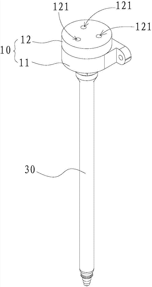
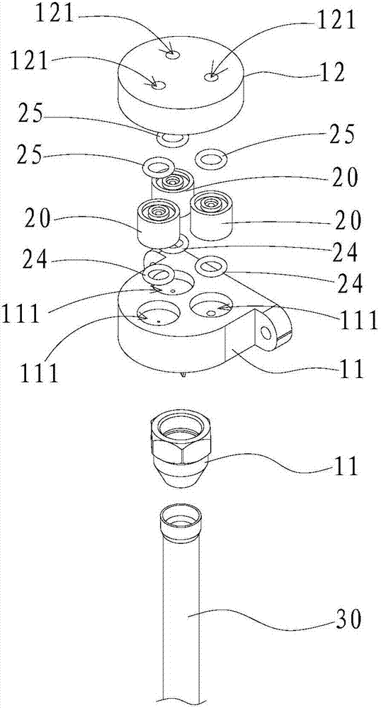
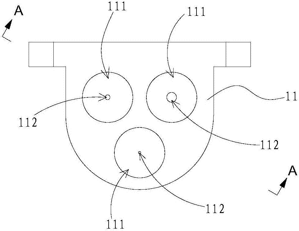
The invention relates to a fluid mixing mechanism. The fluid mixing mechanism comprises a joint assembly, one-way valves and a mixing tube. The joint assembly has two or more fluid channels. A fluid to be mixed is fed into the fluid channel through one end of the fluid channel. The one-way valves comprise two or more valves. The one-way valves are corresponding to the fluid channels. The one-way valves are arranged in the fluid channels. The mixing tube is communicated with the other end of the fluid channel. After the fluid to be mixed enters the fluid channels of the joint assembly, the fluid channels are provided with the one-way valves so that the fluid to be mixed only can flow along a single direction and is mixed in the mixing tube and countercurrent phenomenon is avoided. In preparation of coagulated mixed glue or mixed slurry, the fluid mixing mechanism prevents coagulation and clogging caused by the mixed glue or mixed slurry countercurrent flowing into a feeding channel or a feeding pipe.

Description

technical field [0001] The invention relates to the technical field of fluid mixing, in particular to a fluid mixing mechanism. Background technique [0002] Traditional fluid mixing mechanisms include mixing tubes. The mixing tube is provided with more than two feeding passages, and the feeding passages are connected to the storage device through the feeding pipes. The fluid stored in the storage device enters the mixing tube through the feeding channel for mixing. However, when the fluid mixing mechanism is used to make coagulating mixed glue or mixed slurry, if the mixed glue or mixed slurry flows back into the feed channel and the feed pipe due to the pressure difference between the two ends of the mixing tube, it will There is a bad phenomenon of solidification and blockage in the feed pipe or feed channel. Contents of the invention [0003] Based on this, it is necessary to overcome the defects of the prior art and provide a fluid mixing mechanism, which can avoid...

Claims


Application Information

Patent Timeline
IPC IPC(8): B01F5/00B01F3/08F16K15/02
CPCF16K15/025B01F23/405B01F2025/9191B01F25/1051B01F2035/351
Inventor 李辉雷土成
Owner GUANGZHOU YONGHEXIANG AUTOMATION EQUIP TECH CO LTD
Why Eureka
Try Eureka