
Ultrasonic flaw-detection coupling agent spray head

A technology of ultrasonic and couplant, which is applied in the direction of material analysis, measuring devices, and instruments using sound waves/ultrasonic waves/infrasonic waves. It can solve problems such as loss of couplant, difficulty in detection work, easy smearing and unevenness, and reduce the use of Quantity, reducing the possibility of defects being missed, easy to fix and reliable results

Pending Publication Date: 2017-08-25
STATE GRID ZHEJIANG TONGLU POWER SUPPLY +2
View PDF5 Cites 1 Cited by
  • Summary
  • Abstract
  • Description
  • Claims
  • Application Information

AI Technical Summary

Problems solved by technology

[0002] The conventional couplant application method is realized by manually squeezing the couplant bottle. Since the installation position of the porcelain bottle is relatively high, and the flaw detection surface is between the upper and lower flanges of the porcelain bottle and the porcelain skirt, the space is extremely narrow, so it is applied by manually squeezing the couplant bottle. It is relatively difficult to apply the couplant, and it is easy to apply unevenly, and due to the time difference between the application of the couplant and the detection of the probe, the couplant will hang down and be lost, which brings difficulties to the detection work

Method used


Image

  • Ultrasonic flaw-detection coupling agent spray head
  • Ultrasonic flaw-detection coupling agent spray head
  • Ultrasonic flaw-detection coupling agent spray head

Examples


Embodiment Construction

[0032] The present invention will be further described in detail below in conjunction with the accompanying drawings and specific embodiments.

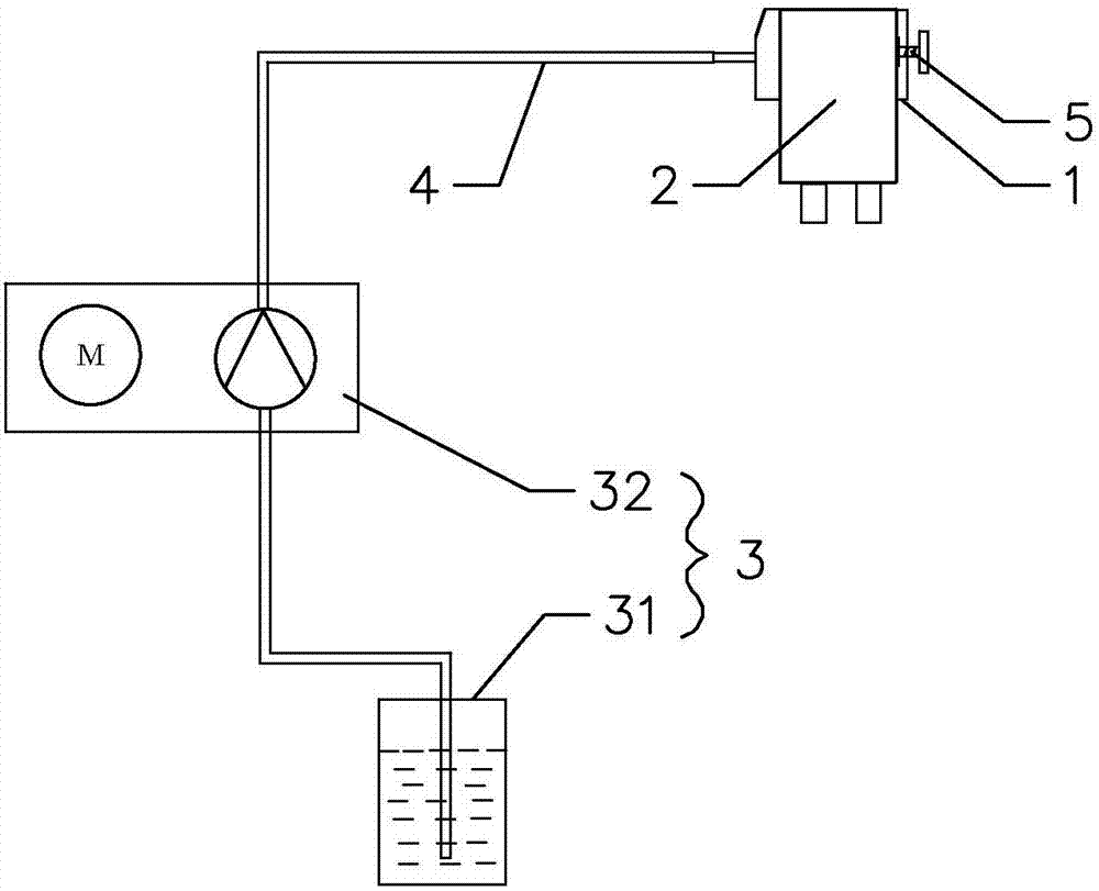
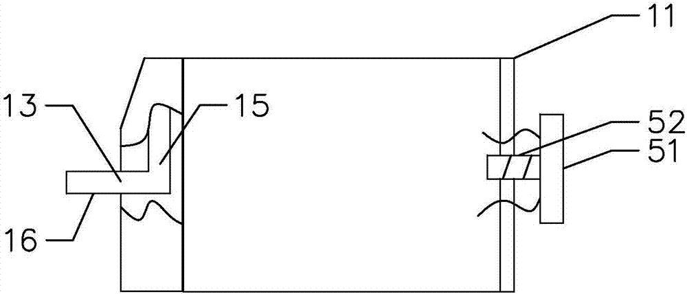
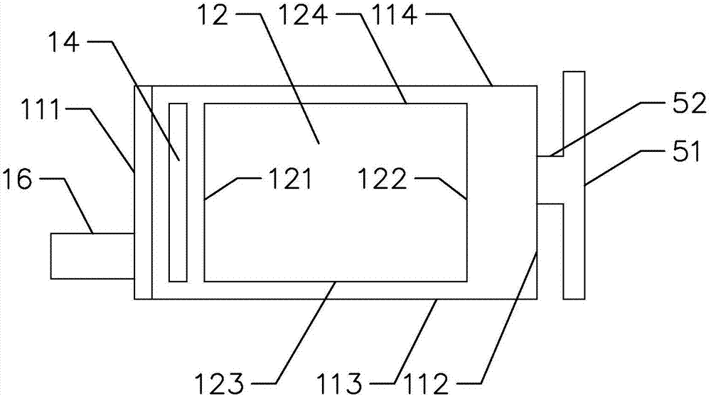
[0033] Such as Figures 1 to 4 As shown, the present invention provides an ultrasonic flaw detection couplant nozzle 1, including a body 11, an installation cavity 12 arranged on the body 11 and used for installing an ultrasonic probe 2, specifically, refer to image 3 The horizontal projection of the main body 11 is rectangular and includes the left side wall 111, the right side wall 112, the front side wall 113 and the rear side wall 114. The main body 11 is a metal body and an insulating body, specifically an aluminum body, which can ensure The strength of the nozzle improves the durability of the nozzle, and ensures that the nozzle will not get an electric shock during detection, improving the safety of use. The installation cavity 12 includes a left inner wall 121, a right inner wall 122, a front inner wall 123, and a rear inner ...


PUM


Abstract

The invention provides an ultrasonic flaw-detection coupling agent spray head. The spray head comprises a body and a mounting cavity, wherein the mounting cavity is formed in the body and is used for mounting an ultrasonic probe, a liquid inlet and liquid spray hole which are communicated with a coupling agent automatic liquid feeding device are formed in the body, a liquid spray channel communicated with the liquid inlet and the liquid outlet is formed in the body, the liquid inlet is formed in one side of the body, the liquid spray hole is formed in the top of the body and is aligned with the front end of the ultrasonic probe after the ultrasonic probe is mounted in place, and a locking component for fixing the ultrasonic probe into the mounting cavity is arranged on the other side of the body. Therefore, in a flaw detection process of a support pillar isolator or a ceramic sleeve, the problems that the sagging and loss of the coupling agent are caused due to time difference between the smearing of the coupling agent and the detection of the ultrasonic probe are avoided, and the support pillar isolator or the ceramic sleeve can be effectively, rapidly and uniformly smeared with the coupling agent, so that the accuracy during the detection of the ultrasonic probe is improved; and the use amount of the coupling agent in the detection process is reduced, so that the wasting of the coupling agent is reduced, and the detection cost is lowered.

Description

technical field [0001] The invention relates to the flaw detection technology of post insulators and porcelain sleeves, in particular to a coupling agent nozzle for ultrasonic flaw detection. Background technique [0002] The conventional couplant application method is realized by manually squeezing the couplant bottle. Since the installation position of the porcelain bottle is relatively high, and the flaw detection surface is between the upper and lower flanges of the porcelain bottle and the porcelain skirt, the space is extremely narrow, and the couplant bottle is applied manually. The smearing of the couplant becomes relatively difficult, and it is easy to smear unevenly. Due to the time difference between the couplant application and the probe detection, the couplant will hang down and be lost, which brings difficulties to the detection work. Contents of the invention [0003] The object of the present invention is to provide a couplant nozzle for ultrasonic flaw det...

Claims


Application Information

Patent Timeline
Patent Type & Authority Applications(China)
IPC IPC(8): G01N29/28
CPCG01N29/28
Inventor 钱家阳方明俊余卫成吴望业范镔李宁李杨刘斐程燕云孙炳伟洪杰
Owner STATE GRID ZHEJIANG TONGLU POWER SUPPLY
Learn More