Eureka AIR delivers breakthrough ideas for toughest innovation challenges, trusted by R&D personnel around the world.

Combined type high-voltage DC circuit breaker with self-energizing ability, and self-energizing strategy thereof

A high-voltage direct current, circuit breaker technology, applied in the direction of emergency protection circuit devices, electrical components, etc., can solve problems such as limiting the application of DC circuit breakers, and achieve the effects of avoiding insulation and withstand voltage problems, ensuring stability, and avoiding insulation problems

Active Publication Date: 2017-08-22
ZHEJIANG UNIV
View PDF7 Cites 19 Cited by
  • Summary
  • Abstract
  • Description
  • Claims
  • Application Information

AI Technical Summary

Problems solved by technology

Aiming at the problems existing in the prior art, the Chinese patent with the publication number CN104767185A proposes a combined high-voltage DC circuit breaker suitable for DC grids. The circuit breaker refers to the design concept of the hybrid high-voltage DC circuit breaker, and its The main components have been reconfigured and improved, especially suitable for DC grid systems with complex grid structures
[0005] At present, regardless of the hybrid high-voltage DC circuit breaker or the combined high-voltage DC circuit breaker, it cannot operate successfully in the high-voltage field, such as a DC power grid with a DC voltage of 500kV. The fundamental reason is that the current project uses external power supply. , to supply energy for the drive circuit of the IGBT in the circuit breaker, but since the circuit breaker needs to be connected in series in the DC line, and the DC voltage level is relatively high, higher requirements are placed on the insulation and withstand voltage of the external power supply circuit. Unsatisfactory; this defect greatly limits the application of DC circuit breakers in the field of high voltage technology

Method used


Image

  • Combined type high-voltage DC circuit breaker with self-energizing ability, and self-energizing strategy thereof
  • Combined type high-voltage DC circuit breaker with self-energizing ability, and self-energizing strategy thereof
  • Combined type high-voltage DC circuit breaker with self-energizing ability, and self-energizing strategy thereof

Examples


Embodiment Construction

[0031] In order to describe the present invention more specifically, the technical solutions of the present invention will be described in detail below in conjunction with the accompanying drawings and specific embodiments.

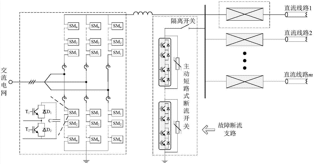
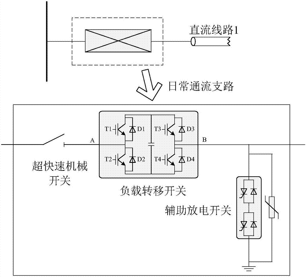
[0032] like figure 1 and figure 2 As shown, the combined high-voltage DC circuit breaker with self-supply capability of the present invention is composed of a fault interruption branch and a daily flow branch, wherein the fault interruption branch includes an active short-circuit interruption switch and its isolating switch, and the daily passage The flow branch includes an ultra-fast mechanical switch, a load transfer switch and an auxiliary discharge switch; the high-voltage end of the active short-circuit breaker is connected to the DC bus through an isolation switch, and the low-voltage end is directly grounded; one end of the ultra-fast mechanical switch is connected to the DC bus, and the other is connected to the DC bus. One end is connected to o...


PUM


Abstract

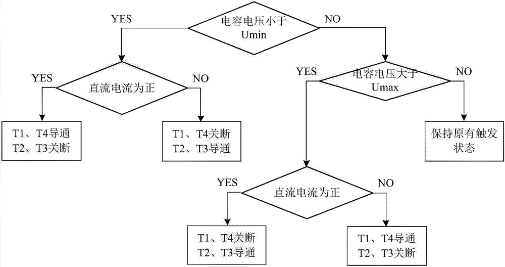
The invention discloses a combined type high-voltage DC circuit breaker with a self-energizing ability, and a self-energizing strategy thereof. According to the combined type high-voltage DC circuit breaker and the self-energizing strategy thereof, a daily through-current branch of a traditional combined type high-voltage DC circuit breaker is improved, a load transfer switch is changed from the original mode of IGBT series connection to a mode of full-bridge submodule series connection, and the corresponding self-energizing strategy is designed, so that capacitors in submodules operate in an energized manner under normal working condition. The load transfer switch of the circuit breaker typology is energized by means of the capacitors of the submodules directly without the need of external power supply, the insurmountable insulation problem in engineering is avoided, and the application prospect of the circuit breaker in a high-voltage DC power grid can be improved.

Description

technical field [0001] The invention belongs to the technical field of power electronic systems, and in particular relates to a combined high-voltage direct current circuit breaker with self-supply capability and its self-supply strategy. Background technique [0002] The DC fault self-clearing capability of the DC grid is an important technical problem related to the development prospect of the DC grid. Compared with traditional AC transmission, there are two main technical difficulties in the development of high-voltage DC circuit breakers suitable for DC grids: (1) The damping of DC grids is low, and its fault development speed is faster, which poses a problem for the operating speed of circuit breakers. Higher requirements; (2) Since the DC transmission has no current zero crossing point, its fault arc is more difficult to extinguish. At present, the research programs of high-voltage DC circuit breakers mainly focus on three types, namely, traditional mechanical circuit...

Claims


Application Information

Patent Timeline
Patent Type & Authority Applications(China)
IPC IPC(8): H02H7/26
CPCH02H7/268
Inventor 徐政刘高任肖晃庆肖亮
Owner ZHEJIANG UNIV
Why Eureka
Eureka Blog
Learn More