
Temperature display device of vehicle

A display device, vehicle technology, applied in the direction of temperature measurement in motors, temperature measurement of moving fluids, thermometers, etc., can solve problems such as occupant anxiety

Inactive Publication Date: 2017-08-22
MAZDA MOTOR CORP
View PDF5 Cites 4 Cited by
  • Summary
  • Abstract
  • Description
  • Claims
  • Application Information

AI Technical Summary

Problems solved by technology

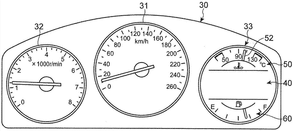
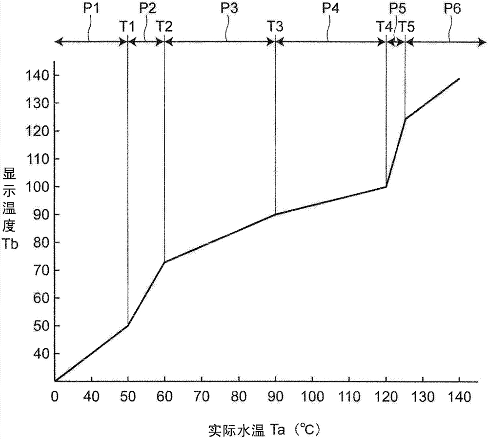
Such a change in cooling water temperature itself is not particularly problematic, but if the display of the water temperature display section changes drastically together with the cooling water temperature, it may cause uneasiness to the occupants.

Method used


Image

  • Temperature display device of vehicle
  • Temperature display device of vehicle
  • Temperature display device of vehicle

Examples


Embodiment Construction

[0082] Hereinafter, embodiments of the present invention will be described with reference to the drawings.

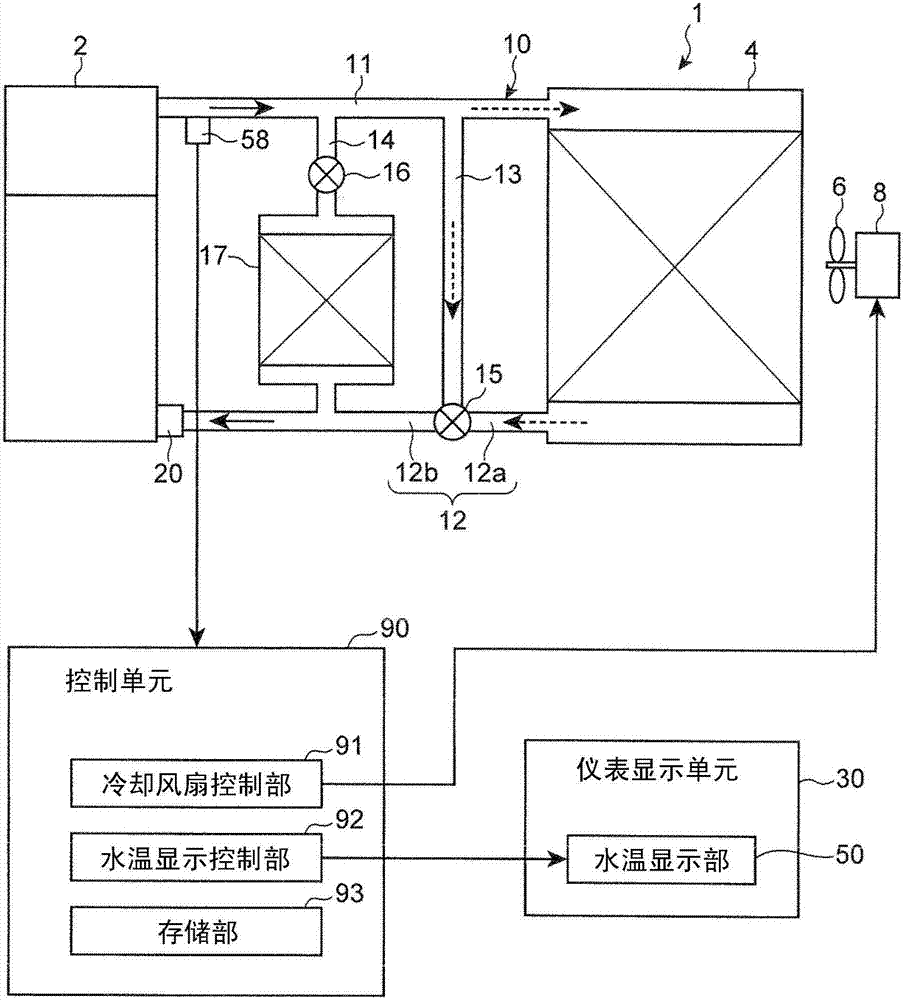
[0083] Such as figure 1 As shown, the engine cooling system 1 includes: a flow path 10 for cooling water of the engine 2; a radiator 4 for cooling the cooling water flowing through the flow path 10; and a water pump 20 provided in the flow path 10.

[0084] The cooling water flowing through the flow path 10 is cooled by the vehicle driving wind when passing through the radiator 4, or, as necessary, the cooling fan 6 is driven to rotate by the motor 8 to be forcedly cooled.

[0085] The water pump 20 is connected to the crankshaft of the engine 2 through a timing belt. Thereby, the water pump 20 can be driven by the drive of the engine 2, and the cooling water in the flow path 10 can be circulated by the drive of the water pump 20.

[0086] The flow path 10 includes: a first path 11 for introducing cooling water from the engine 2 side to the radiator 4 side; a second path 12 for...


PUM


Abstract

A temperature display device of a vehicle is provided, which includes a temperature sensor for detecting a temperature of coolant of an engine, the coolant being switched in circulation state by opening and closing a thermostat, between a first state where the coolant is circulated through a radiator and a second state where the coolant is circulated bypassing the radiator, a display unit for displaying a temperature of the coolant, and a controller for controlling a display mode of the display unit based on the detected temperature by the temperature sensor. When the detected temperature changes within a first temperature range where the thermostat is in an open state, the controller changes the displayed temperature on the display unit by less than the change of the detected temperature.

Description

Technical field [0001] The present invention relates to a temperature display device for a vehicle that displays the temperature of cooling water of an engine. Background technique [0002] Generally, a thermostat is provided in an engine cooling system that circulates cooling water between the engine and the radiator. In this type of engine cooling system, as a flow path from the engine to the engine, a flow path through the radiator and a flow path bypassing the radiator are provided. The switching of these flow paths is performed by opening and closing the thermostat, thereby enabling Switching between a first state in which the cooling water of the engine is circulated via the radiator and a second state in which the cooling water of the engine is circulated bypassing the radiator. [0003] As a thermostat installed in an engine cooling system, a type that opens and closes by expansion and contraction of thermally expandable materials such as wax is widely used. In this type ...

Claims


Application Information

Patent Timeline
Patent Type & Authority Applications(China)
IPC IPC(8): F01P11/16
CPCF01P11/16G01K1/02G01K13/02G01K2205/00G01K13/026B60Y2400/302B60Y2400/92G01M15/048
Inventor 渡濑博之
Owner MAZDA MOTOR CORP
Learn More