
Vertical shaft non-suspension segmented stepping descending type integral metal formwork

A technology of metal formwork and formwork, which is applied in wellbore lining, underground chambers, shaft equipment, etc. It can solve problems such as poor effect, slurry leakage in the net size of the wellbore, and influence on the thickness of the wellbore wall, etc.

Active Publication Date: 2017-08-22
CHINA COAL NO 5 CONSTR
View PDF10 Cites 8 Cited by
  • Summary
  • Abstract
  • Description
  • Claims
  • Application Information

AI Technical Summary

Problems solved by technology

The template has major defects, mainly in the following two aspects: 1. When pouring the concrete shaft wall, the 360mm arc length at the T-shaped plate affects the thickness of the shaft wall and the net size of the shaft, and there is a problem of slurry leakage, which affects the pouring quality of the shaft wall. , the follow-up processing is time-consuming and material-intensive and the effect is not good; 2. When pouring the concrete shaft wall, the formwork is supported on the floating gangue at the bottom of the shaft by the blade foot, and the concrete is solidified after demoulding. While waiting for the concrete to solidify, the workers enter the next process— —Drilling and blasting, the blasting point is too close to the template, there are potential safety hazards

Method used


Image

  • Vertical shaft non-suspension segmented stepping descending type integral metal formwork
  • Vertical shaft non-suspension segmented stepping descending type integral metal formwork
  • Vertical shaft non-suspension segmented stepping descending type integral metal formwork

Examples


Embodiment Construction

[0021] The following is a specific example of the present invention, and the present invention will be further described in conjunction with the accompanying drawings.

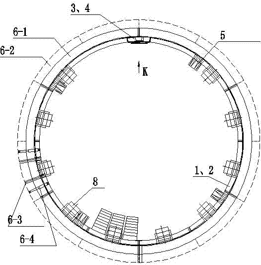
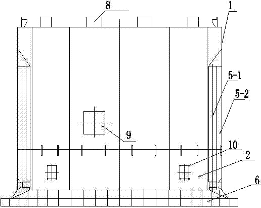
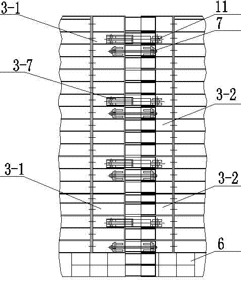
[0022] Such as figure 1 , figure 2 and image 3 As shown in the figure, there is a kind of step-down overall metal formwork without suspension in vertical shaft. The upper C-shaped formwork 1 and the lower C-shaped formwork 2 are both cylindrical with an opening. The upper C-shaped formwork 1 and the lower C-shaped formwork 2 The whole is rigidly connected by steel structure. The opening of the upper C-shaped formwork 1 is connected with an upper shrinkage opening closing module 3, and the opening of the lower C-shaped formwork 2 is connected with a lower shrinking opening closing module 4; The demoulding oil cylinder 11 that controls the shrinkage of the upper shrinkage port closing module 3 and the lower shrinkage port closing module 4 . The oil cylinder in the device can be controlled and provided with...


PUM


Abstract

The invention discloses a vertical shaft non-suspension segmented stepping descending type integral metal formwork with a convergent opening being in a door bolt type and belongs to the technical field of vertical shaft engineering construction. An opening of an upper C-type formwork is connected with an upper convergent opening sealing module. An opening of a lower C-type formwork is connected with a lower convergent opening sealing module. The upper convergent opening sealing module and the lower convergent opening sealing module are each provided with a demoulding oil cylinder. The inner walls of the upper C-type formwork and the lower C-type formwork are connected with a plurality of evenly distributed longitudinal supporting guide devices used for driving the upper C-type formwork and the lower C-type formwork to move vertically and oppositely. A circular-ring-shaped supporting shoe, a silica gel plate and a silica gel air bag are fixed to the lower end of the lower C-type formwork. By means of the vertical shaft non-suspension segmented stepping descending type integral metal formwork, the problems of unevenness of a convergent opening of an integral movable metal formwork with a T-plate, slurry leakage and poor operability and usability in the prior art are solved, and the problem that when a formwork is suspended with a wire rope, the formwork needs to be erected on floating rock at the shaft bottom, and the requirement for safe explosion distance cannot be met is solved.

Description

technical field [0001] The invention relates to the technical field of shaft engineering construction, in particular to a non-suspension segmental step-down integral metal formwork for a shaft with a door plug-in constriction opening. Background technique [0002] At present, the pouring concrete shaft wall of vertical shaft construction mostly adopts metal integral mobile formwork, which is composed of standard block straight formwork, shrinkage left formwork, shrinkage right formwork, shrinkage mouth and T-shaped board. The formwork adopts the sinking winch and wire rope suspension to move down. The template has major defects, mainly in the following two aspects: 1. When pouring the concrete shaft wall, the 360mm arc length at the T-shaped plate affects the thickness of the shaft wall and the net size of the shaft, and there is a problem of slurry leakage, which affects the pouring quality of the shaft wall. , the follow-up processing is time-consuming and material-intens...

Claims


Application Information

Patent Timeline
Patent Type & Authority Applications(China)
IPC IPC(8): E21D11/10
CPCE21D11/102Y02E10/20
Inventor 桑华杨东兵孟凡良袁兆宽王鹏越江军王者尧付万贵吕红娟马传银
Owner CHINA COAL NO 5 CONSTR
Learn More