Lock handle

A technology for locking handles and handles, which is applied in the field of lock handles and can solve problems such as handle sagging

Inactive Publication Date: 2017-08-22
ALLEGION SECURITY TECH CHINA
View PDF5 Cites 0 Cited by
  • Summary
  • Abstract
  • Description
  • Claims
  • Application Information

AI Technical Summary

Problems solved by technology

[0006] The technical problem to be solved by the present invention is to overcome the problems existing in the prior art, provide a new lock handle, and solve the problem of handle drooping in the prior art

Method used


Image

  • Lock handle
  • Lock handle
  • Lock handle

Examples


Embodiment Construction

[0019] In order to make the technical means, creative features, goals and effects achieved by the present invention easy to understand, the present invention will be further described below in conjunction with specific illustrations.

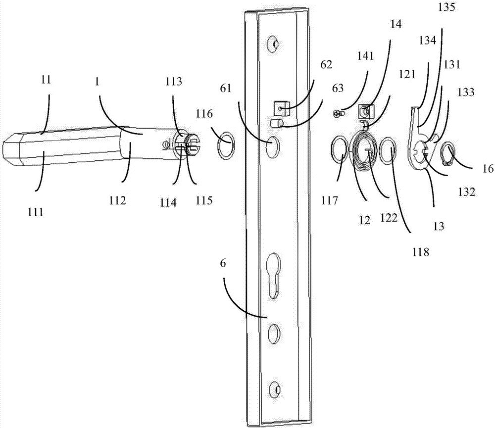
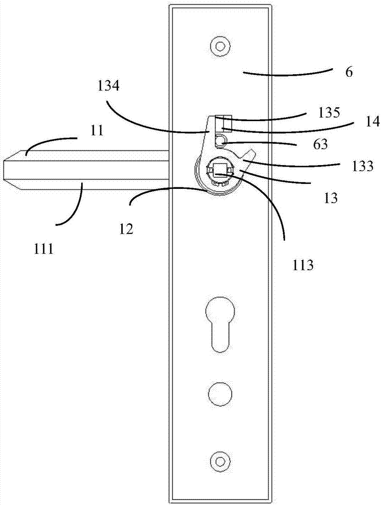
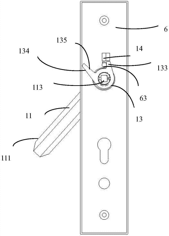
[0020] figure 1 It is an exploded schematic view of the lock handle of the present invention, which also includes a panel 6 as shown in the figure. see figure 1 , according to the lock handle 1 of the present invention, can be inserted into the hole of the panel 6 for opening and locking the door. The lock handle 1 includes a handle 11 , a spring 12 and a limiting piece 13 , which are serially connected sequentially and installed on the panel 6 . The handle 11 includes a handle rod 111 and a handle body 112, the handle body 112 is inserted into the hole 61 of the panel 6, and the handle rod 111 is available for holding. Because the existing handle 11 is easy to hang down, the lock handle 1 is also provided with a magnetic body 14 . The magne...


PUM


Abstract

The invention provides a lock handle, which can be installed on the lock panel, the handle includes a handle, one end of the handle is installed on the panel, the handle includes a handle body and a handle bar, the handle also includes a magnetic body, and the magnetic body is installed on the panel On the handle body, an adsorption surface is provided on the side close to the original position. When the handle of the handle is close to the reset original position, the magnetic body can absorb the adsorption surface. The handle has a simple structure and effectively solves the problem of the handle drooping.

Description

technical field [0001] The invention relates to the technical field of doors and windows, in particular to a lock handle. Background technique [0002] On facilities such as doors and windows, in order to facilitate people to open or close doors and windows, handles are usually provided, and people hold the handle of the handle to push the doors and windows open or close easily. [0003] Locks can be set on the doors and windows, and the handle of the handle can be turned to drive the locks on the doors and windows to rotate. When the locks rotate a certain angle, they can be opened. The handle of the handle is generally hoped to be in a horizontal position, and it is hoped that when the door is opened from the inside of the door and window, the door can be opened by turning the handle. When the door and window are locked, the door and window can be opened by turning the handle from the inside of the door and window. [0004] The handles of common locks currently on the ma...

Claims


Application Information

Patent Timeline
IPC IPC(8): E05B1/00E05B3/00
CPCE05B1/00E05B3/00
Inventor 刘锋
Owner ALLEGION SECURITY TECH CHINA
Why Eureka
Try Eureka