Double-layer retracing driven two-stage rotation finger mechanism
A finger, double-layer technology, applied in the field of two-stage rotary finger mechanism, can solve the problems of large space occupation and large joint influence, and achieve the effect of saving space and simplifying the structure of the manipulator.
- Summary
- Abstract
- Description
- Claims
- Application Information
AI Technical Summary
Problems solved by technology
Method used
Image
Examples
Embodiment 1
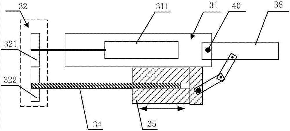
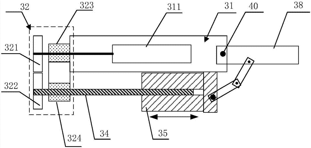
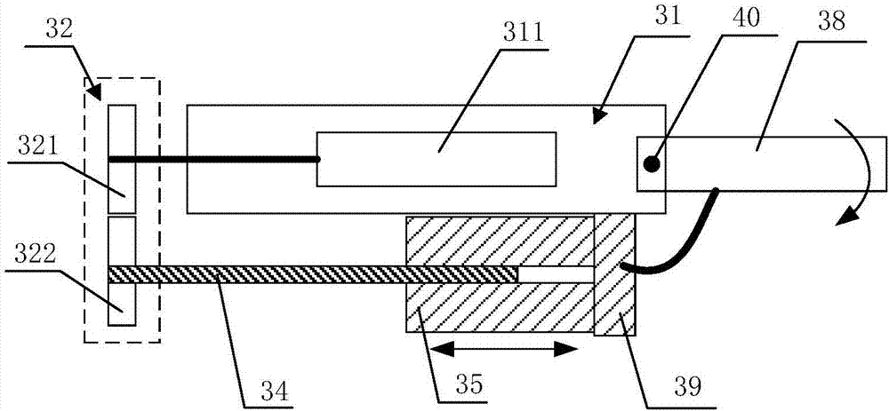
[0038] Such as Figure 1 to Figure 5 As shown, it is a schematic diagram of the principle of the double-layer turn-back driven finger mechanism of the embodiment of the present invention. The double-layer turn-back driven finger mechanism of the embodiment of the present invention includes a finger frame, a gear transmission group, a motor, a screw, and a screw that cooperates with the screw. Nut and finger body. Wherein, the gear transmission set includes a first gear and a second gear that mesh with each other, and the finger body and the finger frame are rotatably connected through a first rotating shaft.
[0039]The motor 311 is fixed in the finger frame 31 and is connected with the first gear 321 of the gear train 32 through an output shaft. In practical applications, since the output speed of the motor 311 may be different from the actual required speed, a deceleration assembly may also be included to adjust the output speed of the motor. The motor 311 and the decelerat...
Embodiment 2
[0049] Compared with Embodiment 1, this embodiment provides an alternative solution in Embodiment 1 regarding the way in which the nut 35 is fixed relative to the finger frame 31 in the radial direction. The fixing of the nut 35 relative to the finger frame 31 in the radial direction means that the nut 35 is constrained in the radial direction and released in the axial direction. When the screw rod 34 rotates, the nut 35 can move in the radial direction. The bottom of the finger frame 31 is provided with a sliding guide rail, and the nut 35 is connected with the finger frame 31 through the sliding guide rail, so that the nut 35 is fixedly connected with the finger frame 31 in the radial direction, and can slide in the axial direction. The sliding guide rail can also not have a load-bearing effect, but only provide a binding effect in the radial direction. More preferably, the nut 35 is clamped on the sliding guide rail, so that the sliding guide rail can play a certain load-bea...
Embodiment 3
[0051] Such as Figure 6 to Figure 11 As shown, it is a schematic diagram of the principle of the double-layer turning back driven finger mechanism of the third embodiment. The difference between this embodiment and the second embodiment is that the finger body of this embodiment includes a base phalanx and a proximal phalanx, and correspondingly, the way the nut drives it is also different.
[0052] The above-mentioned base knuckle 42 is rotatably connected with the finger frame 31 through the first rotating shaft 40, and the base knuckle 42 and the proximal knuckle 43 are rotatably connected through the second rotating shaft 44, and are arranged between the proximal knuckle 43 and the finger frame 31. There is a first pull rod 45, one end of the first pull rod 45 is rotatably connected with the finger frame 31 through the third rotating shaft 46, and the other end of the first pull rod 45 is rotatably connected with the proximal knuckle 43 through the fourth rotating shaft 4...
PUM
 Abstract
Description
Claims
Application Information
 - Generate Ideas
- Intellectual Property
- Life Sciences
- Materials
- Tech Scout
- Unparalleled Data Quality
- Higher Quality Content
- 60% Fewer Hallucinations
Browse by: Latest US Patents, China's latest patents, Technical Efficacy Thesaurus, Application Domain, Technology Topic, Popular Technical Reports.
© 2025 PatSnap. All rights reserved.Legal|Privacy policy|Modern Slavery Act Transparency Statement|Sitemap|About US| Contact US: help@patsnap.com


