Winding mechanism

A technology of winding mechanism and driving mechanism, which is applied in the direction of mechanical equipment, mechanical drive clutches, electrical components, etc., can solve unsolved technical problems and other problems, and achieve the effects of simple structure, improved stability, and reasonable design

Active Publication Date: 2017-08-18
TANAC AUTOMATION
View PDF5 Cites 5 Cited by
  • Summary
  • Abstract
  • Description
  • Claims
  • Application Information

AI Technical Summary

Problems solved by technology

[0009] Although the above-mentioned solution has many advantages above, the above-mentioned solution does not solve the above-mentioned technical problem. Therefore, it is urgent to develop a winding mechanism that can solve the above-mentioned technical problem.

Method used


Image

  • Winding mechanism
  • Winding mechanism
  • Winding mechanism

Examples


Embodiment Construction

[0074] The following are specific embodiments of the invention and in conjunction with the accompanying drawings, the technical solutions of the present invention are further described, but the present invention is not limited to these embodiments.

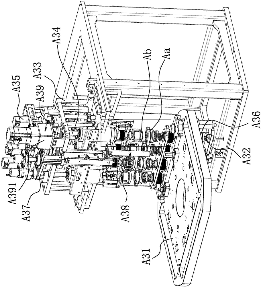
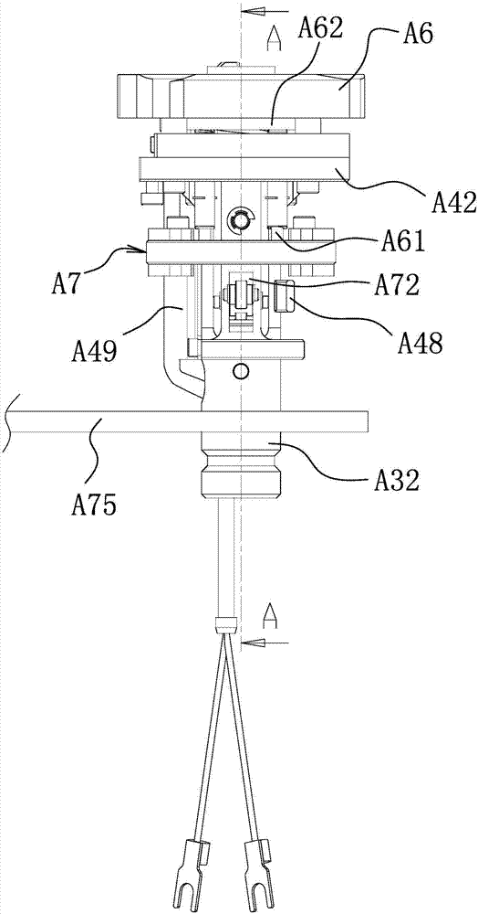
[0075] Such as Figure 1-2 As shown, the winding mechanism includes at least one lower main shaft A32 vertically arranged on the turntable A31 and at least one upper main shaft A34 arranged on the fixed frame A33 and above the lower main shaft A32. The turntable A31 and the fixed frame A33 are respectively Set on the rack (not shown in the figure). The lower main shaft A32 corresponds to the upper main shaft A34 one by one. The upper end of the lower main shaft A32 is provided with a lower jig Aa, and the lower end of the upper main shaft A34 is provided with an upper jig Ab. The upper spindle A34 moves downward so that the upper jig Ab approaches the lifting driver A35 of the lower jig Aa and the lifting driver A35 acts synchron...


PUM


Abstract

The invention belongs to the technical field of a winding machine, and particularly relates to a winding mechanism. The winding mechanism comprises at least one lower main shaft and at least one upper main shaft, wherein the lower main shaft is vertically arranged on a rotation disc, the upper main shaft is arranged on a fixed rack and is arranged above the lower main shaft, the lower main shaft and the upper main shaft are in one-to-one correspondence, a lower jig is arranged at an upper end of the lower main shaft, an upper jig is arranged at a lower end of the upper main shaft, a lifting driver is connected to each upper main shaft and can be used for driving the upper main shaft to downwards move so that the upper jig gets close to the lower jig, the lifting driver synchronously acts, a lower belt transmission structure is connected to the lower main shaft, an upper belt transmission structure is connected to the upper main shaft, a clutch transmission mechanism is connected between the lower belt transmission structure and the upper belt transmission structure and can be used for making the upper main shaft and the lower main shaft synchronously rotated, and the clutch transmission mechanism is connected with a driving terminal. The winding mechanism has the advantage of lower cost and the winding accuracy is improved.

Description

technical field [0001] The invention belongs to the technical field of winding machines, in particular to a winding mechanism. Background technique [0002] Vertical hollow coil winding machine can improve processing efficiency and reduce manufacturing cost. [0003] The winding operation is realized by the upper and lower matching jigs. The upper jig is connected to the upper main shaft, and the lower jig is connected to the lower main shaft. The upper main shaft and the lower main shaft are rotated by different rotational powers, and then the winding operation is performed. [0004] This method has the following defects: [0005] First of all, it is impossible to ensure the synchronous rotation of the upper and lower spindles, which virtually reduces the winding quality of the hollow coil. [0006] Secondly, the cost is higher, that is, the power of two rotations is adopted. [0007] Plus, it's bulky and heavy. [0008] For example, the Chinese patent literature disclo...

Claims


Application Information

Patent Timeline
Patent Type & Authority Applications(China)
IPC IPC(8): H01F41/066H01F41/098F16D11/16
CPCF16D11/16
Inventor 李艳杰唐志勇俞开明徐欢
Owner TANAC AUTOMATION
Why Eureka
Try Eureka