
A process factory model cutting, drawing method and device

A factory model and process technology, applied in the field of large-scale scene drawing, can solve the problems of low efficiency, achieve the effect of increasing the rendering frame rate, reducing the number of traversal and calculation, and improving the efficiency of cropping processing

Active Publication Date: 2020-04-07
北京中科辅龙智能技术有限公司
View PDF3 Cites 0 Cited by
  • Summary
  • Abstract
  • Description
  • Claims
  • Application Information

AI Technical Summary

Problems solved by technology

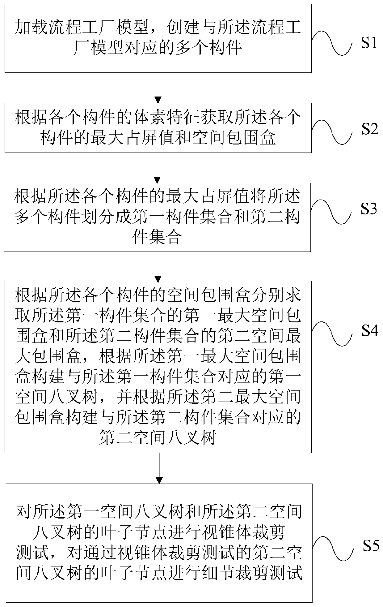
[0004] The embodiment of the present invention provides a process factory model cutting and drawing method and device, which are used to solve the problem of low efficiency of the existing process factory model cutting method

Method used


Image

  • A process factory model cutting, drawing method and device
  • A process factory model cutting, drawing method and device
  • A process factory model cutting, drawing method and device

Examples


Embodiment Construction

[0051] In order to make the purpose, technical solutions and advantages of the embodiments of the present invention clearer, the technical solutions in the embodiments of the present invention will be clearly and completely described below in conjunction with the drawings in the embodiments of the present invention. Obviously, the described embodiments It is a part of embodiments of the present invention, but not all embodiments. Based on the embodiments of the present invention, all other embodiments obtained by persons of ordinary skill in the art without creative efforts fall within the protection scope of the present invention.

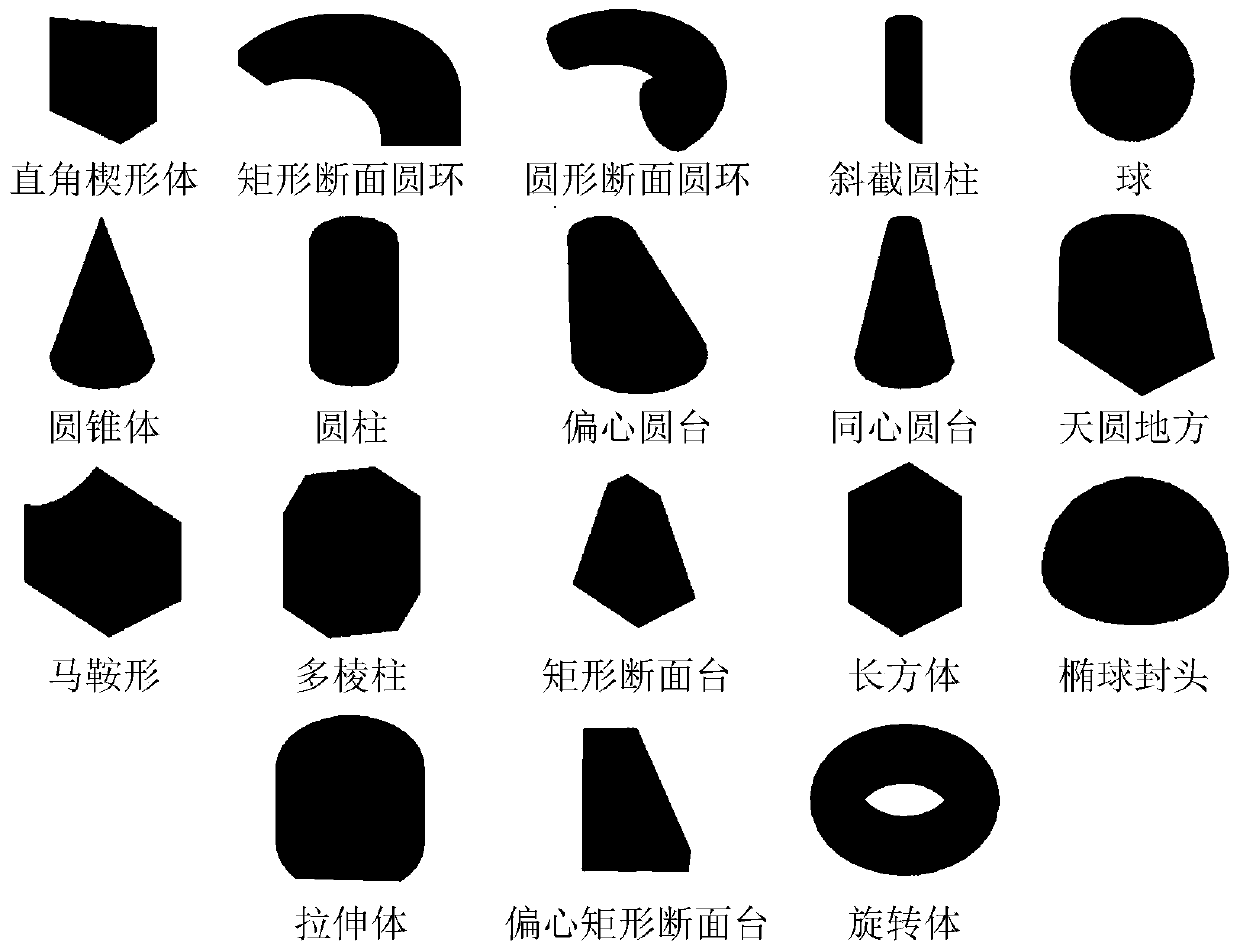
[0052] It should be noted that the components mentioned in the embodiments of the present invention are object collections constituting the process factory model. Pipe fittings, flanges, valves, bolts, nuts and other piping equipment, as well as pumps, fans, blowers, compressors, vacuum equipment, pressure vessels, steam turbines, towers, storage ...


PUM


Abstract

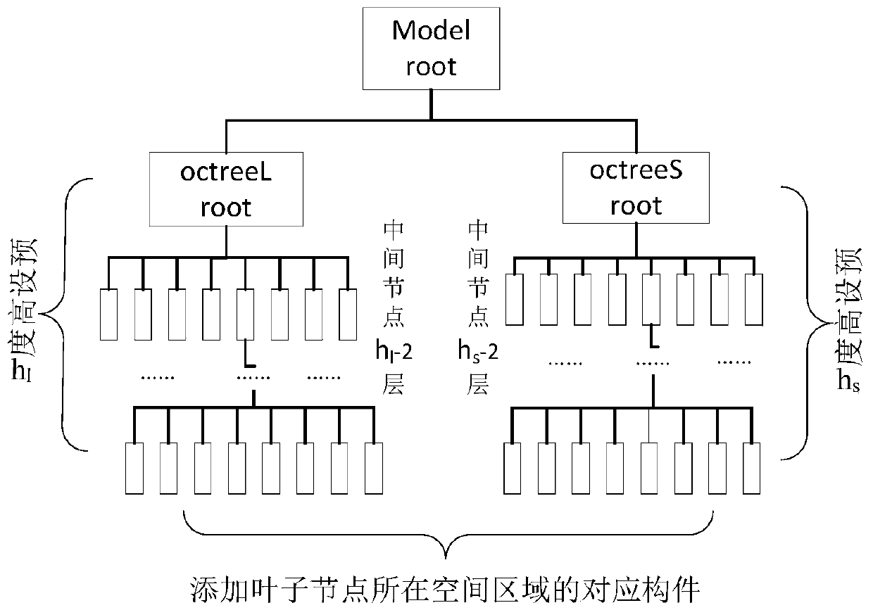
The invention provides a flow factory model cutting and drawing method and device. The method comprises the steps: loading a flow factory model, and building a plurality of members corresponding to the flow factory model; dividing the plurality of members into a first member set and a second member set, building a first spatial octree corresponding to the first member set, and building a second spatial octree corresponding to the second member set; carrying out the view frustum cutting testing of leaf nodes of the first and second spatial octrees, and carrying out the detail cutting testing of the leaf nodes of the second spatial octree passing through the view frustum cutting testing. According to the embodiment of the invention, the method can achieve the estimation of the number of pixels, projected to a curtain at a certain sight distance, of the members according to a maximum screen occupying value through employing the voxel features of the members. The method can quickly discriminate the sizes of the members through the maximum screen occupying value, achieves the complete drawing of the big-size member, and achieves the drawing of the contour of the whole model more precisely. The method achieves the detail cutting of the small-size members according to the number of pixels, improves the cutting processing efficiency, and improves the drawing frame rate.

Description

technical field [0001] The invention relates to the technical field of large-scale scene rendering, in particular to a process factory model cutting and rendering method and device. Background technique [0002] The process factory model refers to a collection of reaction vessels, pipelines and their supports used to manufacture chemical or physical products, and is mainly composed of basic components such as equipment and pipelines. Among them, the pipeline is composed of pipes and components, and the components include pipe fittings, valves, flanges, gaskets, etc., and the pipes are connected through components. Today, the process plant industry has a huge market and occupies a pivotal position in the national economy. The graphic platform of the process factory is an indispensable support foundation for the modern process factory from design, construction to operation management. With the continuous development of the economy and the continuous improvement of the produc...

Claims


Application Information

Patent Timeline
Patent Type & Authority Patents(China)
IPC IPC(8): G06T17/00
CPCG06T17/005
Inventor 唐卫清杜振林李士才周肖彬何涛
Owner 北京中科辅龙智能技术有限公司
Learn More