Real-time urine/body fluid monitoring system

A monitoring system and body fluid technology, applied in the field of medical devices, can solve problems such as large errors and inaccurate measurement

Active Publication Date: 2017-08-18
SHANGHAI YANGPU SHIDONG HOSPITAL
View PDF12 Cites 7 Cited by
  • Summary
  • Abstract
  • Description
  • Claims
  • Application Information

AI Technical Summary

Problems solved by technology

[0003] The present invention aims at the shortcomings of common urine collection bags in the prior art that nurses need to read data repeatedly, resulting in large errors and inaccurate measurement, and provides a monitoring system that can measure urine in real time and measure urine specific gravity, and can also be used for Measure fluid volume and specific gravity data of body fluids

Method used


Image

  • Real-time urine/body fluid monitoring system
  • Real-time urine/body fluid monitoring system
  • Real-time urine/body fluid monitoring system

Examples


Embodiment 1

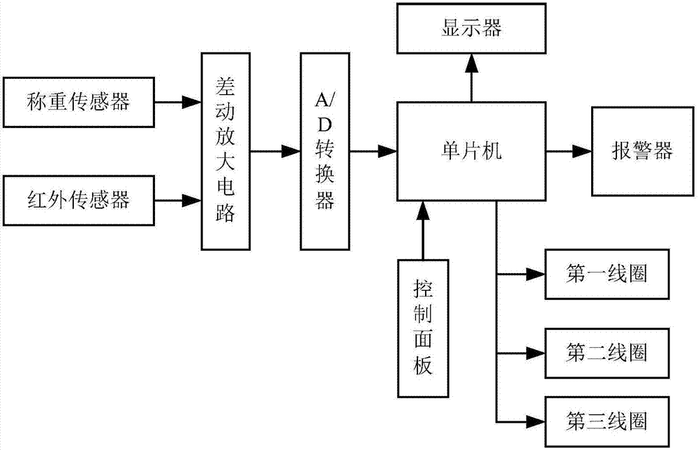
[0043] like Figure 1-3 As shown, this embodiment provides a real-time urine / body fluid monitoring system, which includes a card board 1, two hooks 2, a display 3, a hook 4, an upper drainage tube 12, a transparent tube 7, a bottom End drainage tube 13, a collection device 9 for collecting urine / body fluids (eg urine collection bag), an infrared transmitter 5, an infrared receiver 6, an inlet opening and closing device, an outlet opening and closing device, a ventilation A port opening and closing device, a vent pipe 14, a load cell, a differential amplifier circuit, an A / D converter and a single-chip microcomputer.

[0044] The two hooks 2 are fixed on the upper end of the card board 1 , the two hooks 2 are used for hanging on the bed rail of the patient, the display 3 is embedded in the upper part of the card board 1 , the hook 4 is connected to the display 3 The bottom is connected to the hook 4, the collecting device 7 is suspended on the hook 4, the infrared transmitter ...

Embodiment 2

[0062] The only difference between this embodiment and Embodiment 1 is that:

[0063] The outlet opening and closing device includes a third coil 16, a third baffle 19 and a third conical member 21. The third coil 16 is sleeved on the lower drainage tube 13 and is close to the outlet. The third baffle 19 is placed in the lower drainage tube 13 and is located just below the outlet. Both sides of the third baffle 19 are connected to the bottom outer wall of the transparent tube 7 through third connecting rods. The third conical The member 21 rests on this third baffle 19 .

[0064] The single-chip microcomputer is used to control the third coil 16 to energize after receiving the measurement instruction, so that the third conical member 21 is placed in the outlet and close the outlet, and controls the third coil 16 after receiving the control signal De-energize so that the third conical member 21 falls onto the third baffle 19 and opens the outlet.


PUM


Abstract

The invention discloses a real-time urine/body fluid monitoring system which comprises a clamp plate, at least one hook for hanging on a bed rail, an upper end drainage tube, a transparent tube, a lower end drainage tube, a collecting device, an infrared transmitter, an infrared receiver, an inlet switching device, an outlet switching device, a weighing sensor, a display and a single-chip microcomputer; the single-chip microcomputer receives an measurement instruction and controls the inlet switching device to open the inlet and the outlet switching device to close the outlet, so that urine/body fluid flows in the transparent tube, the infrared transmitter transmits infrared light, and the infrared receiver receives the infrared light and transmits a control signal to the single-chip microcomputer when liquid level reaches set distance; the single-chip microcomputer controls the inlet switching device to close the inlet and the outlet switching device to open the outlet; the weighing sensor detects weight of the urine/body fluid in the collecting device; the single-chip microcomputer calculates a weight value and the amount of urine/body fluid corresponding to the set distance, and urine specific gravity/body fluid specific gravity is obtained. The system can meter urine/body fluid and measure the urine specific gravity/body fluid specific gravity in real time.

Description

technical field [0001] The invention relates to the technical field of medical devices, in particular to a real-time urine / body fluid (wound drainage, pleural effusion, bile, gastric juice, cerebrospinal fluid, etc.) monitoring system for real-time monitoring of human urine or body fluid. Background technique [0002] Urine output is one of the important indicators to measure tissue perfusion and body fluid balance, and can reflect renal function, cardiac function, circulating blood volume, etc. Urine specific gravity determination is mainly used to understand the concentration and dilution functions of the kidneys, and can also be used for auxiliary diagnosis and condition monitoring of certain diseases. Urine specific gravity can fluctuate widely due to diet and drinking, sweating and urination. Therefore, for patients in the intensive care unit, the determination of urine volume and urine specific gravity is particularly important. Existing urine collection usually uses...

Claims


Application Information

Patent Timeline
Patent Type & Authority Applications(China)
IPC IPC(8): G01G17/04A61M1/00
CPCG01G17/04A61M1/70Y02A50/30
Inventor 方旭晨张洁莹王颖肖奕白妮
Owner SHANGHAI YANGPU SHIDONG HOSPITAL
Why Eureka
Try Eureka