A pumpless injection refrigeration system and refrigeration method

A refrigeration system and jet technology, applied in refrigeration and liquefaction, refrigerators, refrigeration components, etc., can solve the problem of high cost of circulating pumps and achieve the effect of improving refrigeration efficiency

Active Publication Date: 2019-10-29
SHANDONG UNIV
View PDF8 Cites 0 Cited by
  • Summary
  • Abstract
  • Description
  • Claims
  • Application Information

AI Technical Summary

Problems solved by technology

[0004] In order to solve the problem of high cost of the circulating pump in the ejector refrigeration system, the inventor tried to replace the circulating pump with a gas-liquid ejector. In the generator, the circulating refrigerant absorbs heat and turns into high-temperature and high-pressure steam, and part of the high-pressure The steam passes through the gas injector, forming a lower pressure at the outlet of the nozzle, so that the low-pressure steam obtained by condensing through the condenser and evaporating through the evaporator is introduced into the gas injector, and the two streams are mixed into one with a lower pressure. The high fluid is discharged into the condenser and condensed into a liquid. A part of the liquid is evaporated by the above-mentioned evaporator, and the other part of the liquid is injected into the replaced gas-liquid ejector by the remaining high-pressure steam from the generator, and the two fluids are fully mixed. After being a stream, it is sent back to the generator for circulation

Method used


Image

  • A pumpless injection refrigeration system and refrigeration method

Examples


Embodiment 1

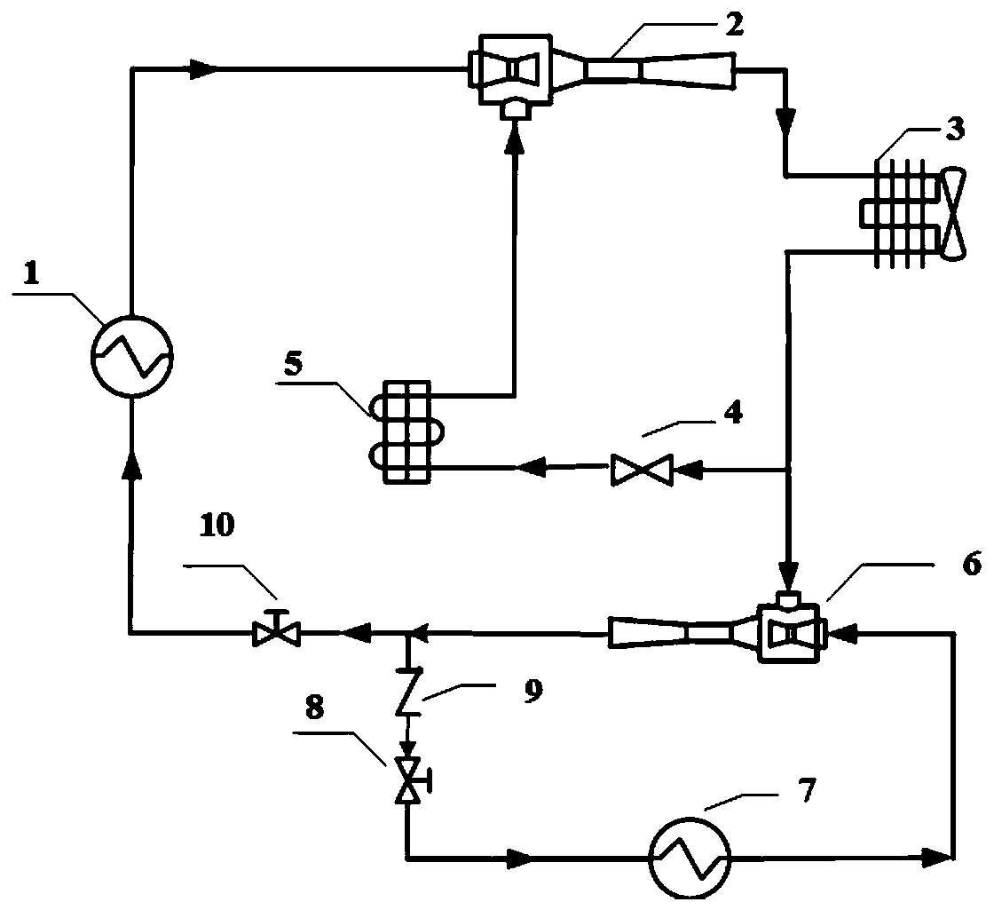
[0027] If R134a is used as the refrigerant, the refrigerant is heated by industrial waste heat (temperature: 120°C) in the first generator 1 to become superheated steam, the temperature of the superheated steam is 90°C, and the pressure is 2.8MPa. The gas injector 2 sucks the refrigerant vapor from the evaporator 5, pressurizes it and enters the condenser 3 together, where it is condensed into a liquid, and the temperature of the liquid is 45°C. Part of the liquid flowing out of the condenser 3 enters the evaporator 5 after being throttled and cooled by the throttle valve 4, and the other part of the liquid is injected and pressurized in the gas-liquid ejector 6 by the steam from the generator 7. The volume ratio of the liquid is 1:2.5. Part of the liquid flowing out of the condenser 3 has a pressure of 2.85 MPa after being pressurized by the gas-liquid ejector 6 . After pressurization, it becomes liquid; it is divided into two paths, one path enters the first generator 1 thr...

Embodiment 2

[0029]If HFO-1234ze(E) is used as the refrigerant, the refrigerant is heated by industrial waste heat (temperature: 80°C) in the first generator 1 to become superheated steam, the temperature of the superheated steam is 55.7°C, and the pressure is 1.15MPa. The gas injector 2 sucks the refrigerant vapor from the evaporator 5, pressurizes it and enters the condenser 3 together, where it is condensed into a liquid, and the temperature of the liquid is 24°C. Part of the liquid flowing out of the condenser 3 enters the evaporator 5 after being throttled and cooled by the throttle valve 4, and the other part of the liquid is injected and pressurized in the gas-liquid ejector 6 by the steam from the generator 7. The volume ratio of the liquid is 1:2.5. Part of the liquid flowing out of the condenser 3 has a pressure of 1.15 MPa after being pressurized by the gas-liquid ejector 6 . After pressurization, it becomes liquid; it is divided into two paths, one path enters the first genera...


PUM


Abstract

The invention discloses a pumpless jet refrigeration system and a refrigeration method, which solve the problems of low refrigeration efficiency and high cost of power equipment circulation pumps in the jet refrigeration system in the prior art, including a first generator, a gas Ejector, condenser, evaporator, second generator and gas-liquid ejector, wherein the outlet of the first generator is connected to the injection steam inlet of the gas ejector, and the outlet of the gas ejector is connected to the inlet of the condenser, The outlet of the condenser is divided into two branches, one branch is connected to the steam inlet of the gas ejector through the evaporator; the other branch is connected to the liquid inlet of the gas-liquid ejector; the outlet of the gas-liquid ejector is divided into Two branches, one branch is connected with the inlet of the first generator, the other branch is connected with the inlet of the second generator, and the outlet of the second generator is connected with the steam inlet of the gas-liquid ejector.

Description

technical field [0001] The invention belongs to the fields of energy technology and refrigeration technology, and in particular relates to a pumpless jet refrigeration system and a refrigeration method. Background technique [0002] As environmental and energy issues become more and more prominent, the shortage of conventional energy has triggered the exploration of new energy and its utilization technology by scholars at home and abroad. Low-grade heat sources such as solar energy and waste heat have attracted widespread attention due to their use in some ejector refrigeration systems such as solar ejection, low-grade waste heat ejection refrigeration systems and their heat pump systems. Among them, the ejector refrigeration system has been favored by the refrigeration industry in the past 10 years due to its simple structure, long service life, and high system stability. However, due to its low refrigeration efficiency, it cannot be widely used. For example, the cooling e...

Claims


Application Information

Patent Timeline
Patent Type & Authority Patents(China)
IPC IPC(8): F25B19/02F25B41/04F25B41/20
CPCF25B19/02F25B41/20
Inventor 赵红霞韩吉田于泽庭赖艳华
Owner SHANDONG UNIV
Why Eureka
Try Eureka