A Gradient Color Spinning Mechanism, Method and Application of Pre-moving Coupling and Wrapping
A gradient color and translation technology, which is applied in the field of coupling-wrapping gradient color spinning mechanism, can solve the problems of large unevenness of yarn, small gradient color span, poor color change effect, etc., and achieve clear gradient color and complete The effect of constant yarn fineness and increased strength
- Summary
- Abstract
- Description
- Claims
- Application Information
AI Technical Summary
Problems solved by technology
Method used
Image
Examples
Embodiment 1
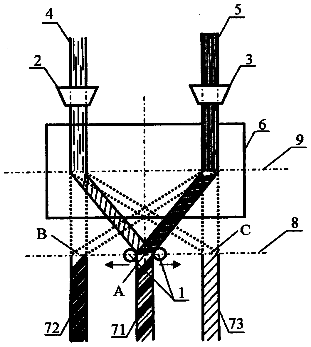
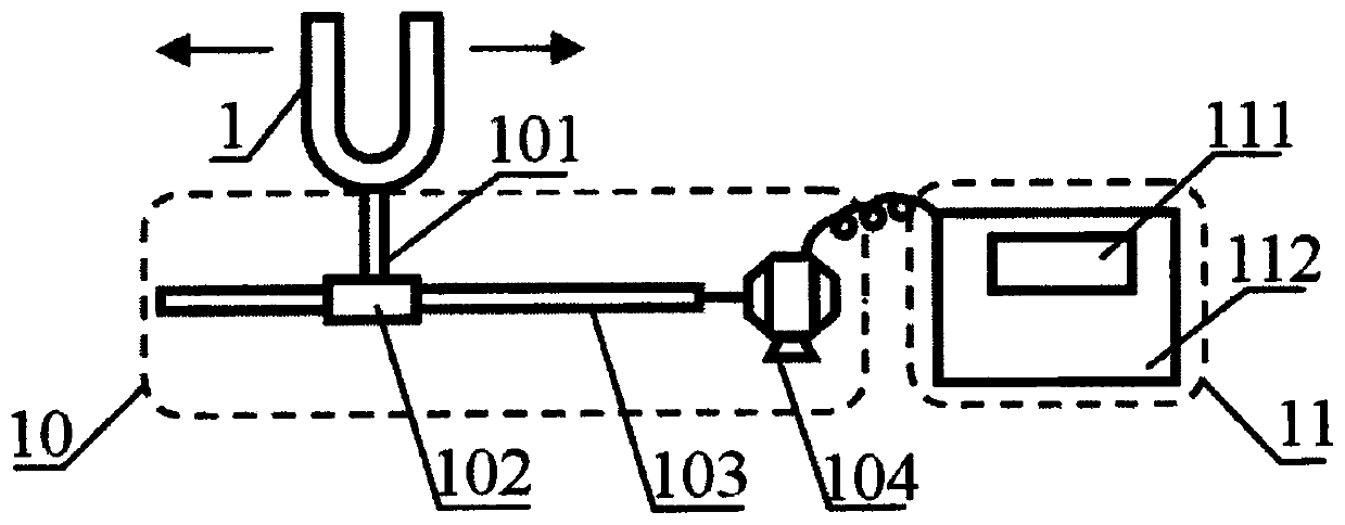
[0057] Take one black and one white cotton fiber roving bobbin, and the composite ratio is 50 / 50. After the two bundles of cotton roving are positioned and gathered by the cluster, they are fed into the nip of the front roller with the natural tension of the drafting and an 8mm spacing. For details, see figure 1 shown. After the two-axis fiber strip exits the nip of the front roller, the twist coefficient α tex is 340, and the spindle speed is 10500rpm, it naturally converges at point A, and the convergence angle of convergence point A is about 60°, which is on the center line. Move the U-shaped needle so that the natural convergence point A is located at the center point of the U-shaped needle. A structural yarn that is naturally coupled and intertwined at the converging point is formed. Then move the U-shaped needle left and right back and forth with the set yarn gradient color waveform (trapezoidal wave) and wavelength (24m) to make a trapezoidal wave gradient, that is, ...
Embodiment 2
[0059] Take one yellow flame-retardant wool roving bobbin and one blue Nomex fiber roving bobbin, and the composite ratio is 50 / 50. After the two bundles of wool roving are positioned and gathered by the bundler, they are fed into the nip of the front roller with the natural tension of the drafting and the distance of 10mm. For details, see figure 1 shown. After the two-axis fiber strip exits the nip of the front roller, the twist coefficient α tex is 345, and the spindle speed is 11500rpm and naturally gathers at point A. Move the U-shaped needle so that the natural convergence point A is located at the center point of the U-shaped needle. A structural yarn that is naturally coupled and intertwined at the converging point is formed. Then use the set yarn gradient color waveform (sine wave) and wavelength (16m), move the U-shaped needle left and right back and forth to make a sine wave gradient, and then measure the coverage c 5 , c 4 / 5 , c 4 value (see Table 1). It can...
Embodiment 3
[0061] Take one white polyester staple fiber roving bobbin and one natural silk fiber roving bobbin respectively, and the composite ratio is 50 / 50. After the two bundles of wool roving are positioned and gathered by the clusterer, they are fed into the nip of the front roller with the natural tension of drafting and 9mm spacing. For details, see figure 1 shown. After the two-axis fiber strip exits the nip of the front roller, the twist coefficient α tex It is 320, and the spindle speed is 10000rpm and naturally gathers at point A. Move the U-shaped needle so that the natural convergence point A is located at the center point of the U-shaped needle. A structural yarn that is naturally coupled and intertwined at the converging point is formed. Then move the U-shaped needle left and right back and forth with the set yarn gradient color waveform (frequency conversion triangular wave) and wavelength (64m) to make a frequency conversion triangle wave gradient, and then measure th...
PUM
| Property | Measurement | Unit |
|---|---|---|
| elongation at break | aaaaa | aaaaa |
| elongation at break | aaaaa | aaaaa |
| elongation at break | aaaaa | aaaaa |
Abstract
Description
Claims
Application Information
 - R&D
- Intellectual Property
- Life Sciences
- Materials
- Tech Scout
- Unparalleled Data Quality
- Higher Quality Content
- 60% Fewer Hallucinations
Browse by: Latest US Patents, China's latest patents, Technical Efficacy Thesaurus, Application Domain, Technology Topic, Popular Technical Reports.
© 2025 PatSnap. All rights reserved.Legal|Privacy policy|Modern Slavery Act Transparency Statement|Sitemap|About US| Contact US: help@patsnap.com


