High speed carrying manipulator used for valve body assembly

一种机械手、阀体的技术,应用在机械手、程序控制机械手、运输和包装等方向,能够解决人力资源浪费、生产效率低下等问题,达到受用寿命长、成本低、提高工作效率的效果

Inactive Publication Date: 2017-08-18
TANGSHAN ZHENGYUAN PIPE IND CO LTD
View PDF6 Cites 2 Cited by
  • Summary
  • Abstract
  • Description
  • Claims
  • Application Information

AI Technical Summary

Problems solved by technology

[0004] The transportation and handling of each component must be operated manually, which leads to serious waste of human resources and low production efficiency.

Method used


Image

  • High speed carrying manipulator used for valve body assembly
  • High speed carrying manipulator used for valve body assembly
  • High speed carrying manipulator used for valve body assembly

Examples


Embodiment Construction

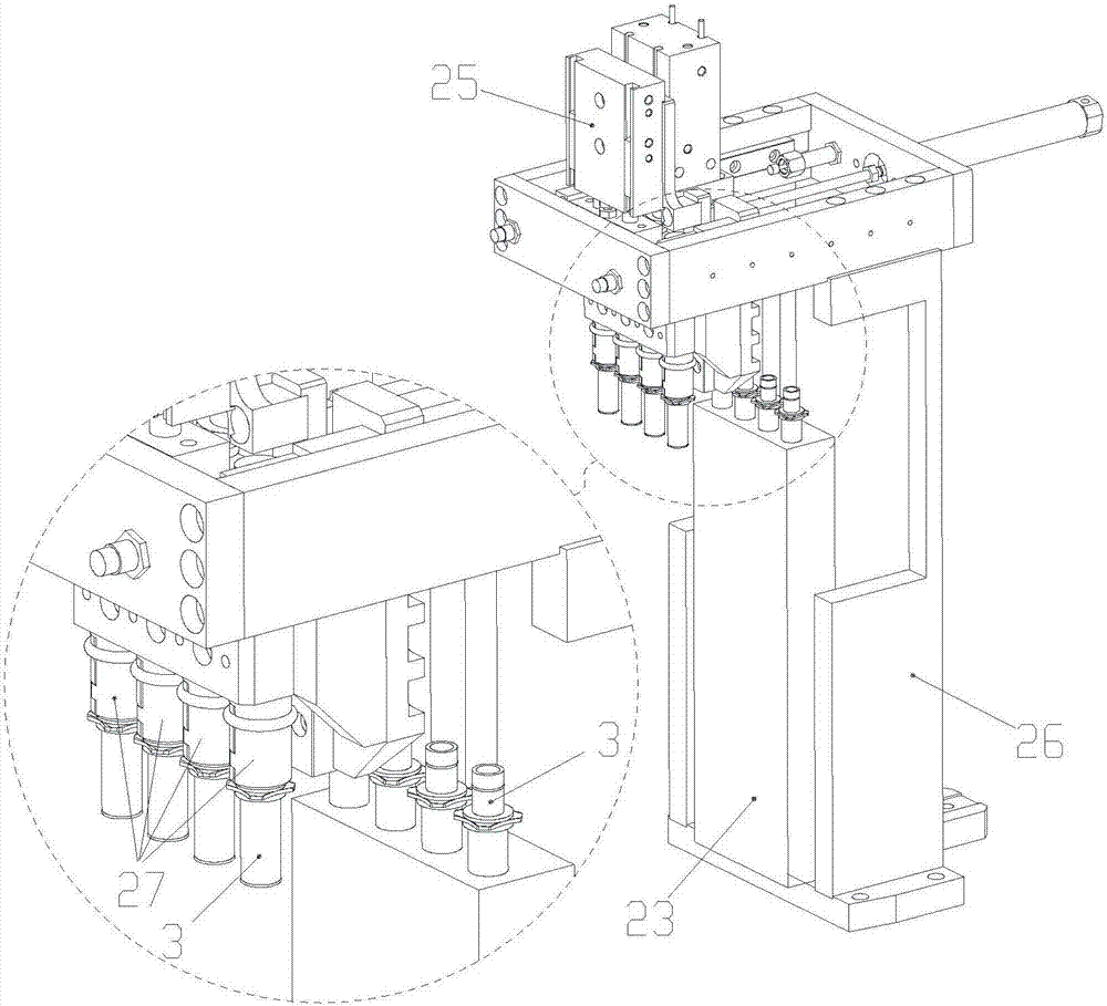
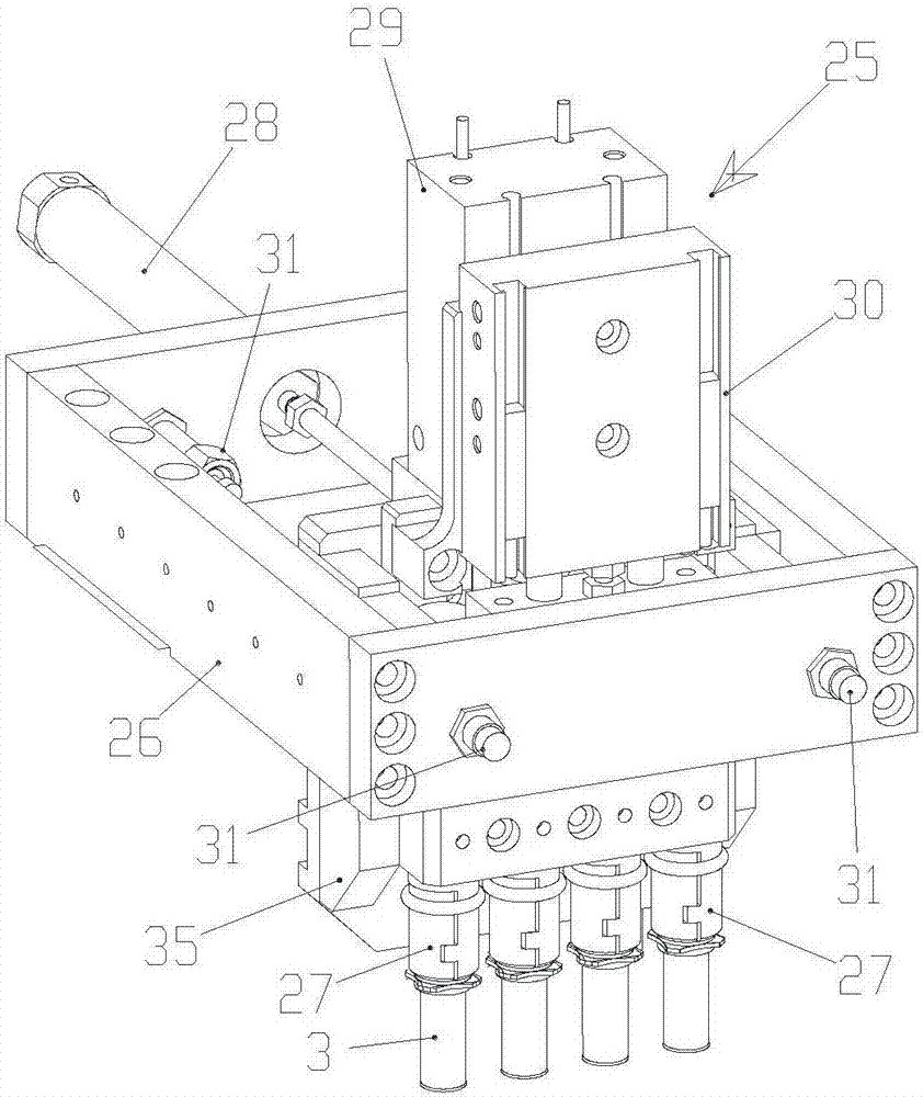
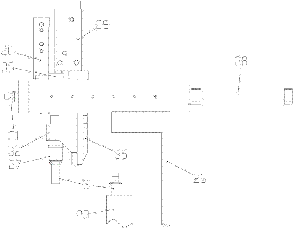
[0035] Embodiments of the present invention will now be described with reference to the drawings, in which like reference numerals represent like elements. As mentioned above, the present invention provides a high-speed handling manipulator for valve body assembly, which is used to move the valve body from one place to another, the valve body is grabbed by the adaptive manipulator, and the valve body is transported to the place to be Assembly position, fully automatic operation, realize unmanned operation, with high work efficiency.

[0036] See Figure 9 , first introduce the structure of the valve body 3, the valve body 3 includes: ear 4, inner hole 5, cylinder 6, the ear 4 is located in the middle and upper part of the valve body 3, the lower part of the ear 3 The part is the cylinder 6 , the inner hole 5 is provided at the lower part of the ear 3 , and the clamping part 24 is at the upper part of the ear 4 . The valve body 3 adopts a precision forging process to prepare ...


PUM


Abstract

The invention is a divisional application, and the application number of the original patent is 201610123878.3. The invention relates to automated assembly equipment, or automated carrying equipment of valve parts, and particularly to a high speed carrying manipulator used for valve body assembly. The high speed carrying manipulator used for valve body assembly comprises a bracket, a self-adaption manipulator used for realizing the carrying function and a fixture body used for clamping and placing valve bodies; the self-adaption manipulator is fixedly connected onto the bracket; the fixture body is positioned within the clamping range of the self-adaption manipulator; the self-adaption manipulator comprises fingers, a front-and-back air cylinder, an up-and-down air cylinder, a finger air cylinder, a palm, a push plate, a connecting plate, a main sliding plate, an auxiliary sliding plate, a transverse linear guide rail, a longitudinal linear guide rail and a discharging shaft. According to the high speed carrying manipulator used for valve body assembly, as restricted by the elasticity of O-shaped hoops, moving fingers can realize the clamping of valve bodies under the function of the elastic force, the clamping action is simple and clear during the overall clamping process, valve bodies can be inserted into the fingers, the fingers can automatically realize the clamping of valve bodies, and meanwhile the fingers can automatically adapt to valve bodies with different outer diameters.

Description

technical field [0001] The patent application for the present invention is a divisional application. The application number of the original case is: 201610123878.3, and the application date is: March 4, 2016. The invention relates to an automatic assembly equipment, in particular to an automatic handling equipment for valve fittings. Background technique [0002] As an important part of the car engine, the gasoline injector plays an important role in the normal running of the car. [0003] Due to the compact structure of the fuel injector spool and the high reliability requirements of the product, in the current traditional process, it is assembled manually. The requirements for automated production are high and difficult. [0004] The transportation and handling of each component must be operated manually, which leads to serious waste of human resources and low production efficiency. [0005] Automated equipment is required to realize the delivery and handling of variou...

Claims


Application Information

Patent Timeline
Patent Type & Authority Applications(China)
IPC IPC(8): B25J9/02B25J9/14B25J15/10B25J19/00
CPCB23P19/007B23P2700/50B25J9/023B25J9/14B25J9/144B25J11/00B25J15/0033B25J15/0052B25J15/0253B25J15/08B25J15/10B25J19/0025
Inventor 邵伟
Owner TANGSHAN ZHENGYUAN PIPE IND CO LTD
Why Eureka
Try Eureka